
Specifications


Table Of Contents
- Table of Contents
- Contents of Kit
- Additional Required Equipment
- Additional Required Tools and Adhesives
- Other Items Needed (not included in the kit)
- Warning
- Before Starting Assembly
- Using the Manual
- Warranty Information
- Section 1: Hinging the Ailerons
- Section 2: Aileron Servo Installation
- Section 3: Aileron Linkages
- Section 4: Hinging the Flaps
- Section 5: Flap Servo Installation
- Section 6: Flap Linkages
- Section 7: Retract Servo Installation
- Section 8: Main Landing Gear and Wheel Doors
- Section 9: Joining the Wing
- Section 10: Mounting the Wing to the Fuselage
- Section 11: Lower Air Intake Installation
- Section 12: Stabilizer Installation
- Section 13: Hinging the Elevators
- Section 14: Hinging the Rudder
- Section 15: Tail Wheel Installation
- Section 16: Fuel Tank Assembly
- Section 17A: Engine Installation
- Section 17B: Engine Installation
- Section 18: Throttle Pushrod and Fuel Tank
- Section 19: Radio Installation
- Section 20: Rudder and Elevator Linkages
- Section 21: Throttle Linkage Installation
- Section 22: Attaching the Cowl
- Section 23: Cockpit Details
- Section 24: Attaching the Canopy
- Section 25: Applying the Decals
- Control Throws and Center of Gravity
- Preflight at the Field
- Adjusting the Engine
- 2003 Official AMA National Model Aircraft Safety Code
Section 16: Fuel Tank Assembly
Section 15: Tail Wheel Installation
41
Step 9
Slide a wheel collar onto the tail gear wire, then the tail
wheel. Finally, slide another wheel collar on, and use an
M3 x 8 screw to secure the outer collar. Use a little
threadlocking compound on the screw to prevent it from
vibrating loose in flight.
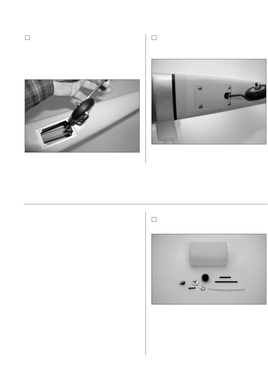
Step 10
Secure the tail gear door cover using four
#2 x 3/8" screws.
Required Parts
• Clunk (fuel pickup) • Metal caps (2)
• Fuel pickup tubing • Fuel tank
• Rubber stopper • M3 x 20 screw
• Metal tubes (short and long)
Required Tools and Adhesives
• Hobby knife • Phillips screwdriver
Note: The stopper provided with the P-51
has three holes that are not bored completely
through the stopper. The holes are for the
fuel pickup, fill, and vent lines. For these
instructions only two holes will be used: one
for the fuel pickup and one for the fuel vent.
Only open the third hole if you are going to
use a separate fill line.
Step 1
Locate the fuel tank parts.