
Specifications


Table Of Contents
- Table of Contents
- Contents of Kit
- Additional Required Equipment
- Additional Required Tools and Adhesives
- Other Items Needed (not included in the kit)
- Warning
- Before Starting Assembly
- Using the Manual
- Warranty Information
- Section 1: Hinging the Ailerons
- Section 2: Aileron Servo Installation
- Section 3: Aileron Linkages
- Section 4: Hinging the Flaps
- Section 5: Flap Servo Installation
- Section 6: Flap Linkages
- Section 7: Retract Servo Installation
- Section 8: Main Landing Gear and Wheel Doors
- Section 9: Joining the Wing
- Section 10: Mounting the Wing to the Fuselage
- Section 11: Lower Air Intake Installation
- Section 12: Stabilizer Installation
- Section 13: Hinging the Elevators
- Section 14: Hinging the Rudder
- Section 15: Tail Wheel Installation
- Section 16: Fuel Tank Assembly
- Section 17A: Engine Installation
- Section 17B: Engine Installation
- Section 18: Throttle Pushrod and Fuel Tank
- Section 19: Radio Installation
- Section 20: Rudder and Elevator Linkages
- Section 21: Throttle Linkage Installation
- Section 22: Attaching the Cowl
- Section 23: Cockpit Details
- Section 24: Attaching the Canopy
- Section 25: Applying the Decals
- Control Throws and Center of Gravity
- Preflight at the Field
- Adjusting the Engine
- 2003 Official AMA National Model Aircraft Safety Code
Section 16: Fuel Tank Assembly
43
Step 7
Carefully insert the stopper assembly into the fuel tank.
Note the position of the vent tube; it must be up at the top
portion of the fuel tank to function properly. Also, it may
be necessary to shorten the length of the fuel pickup
tubing to make sure the clunk does not rub against the
back of the fuel tank. You should be able to turn the tank
to any attitude and the clunk will fall to the lowest point.
(All directions except for having the stopper facing down.)
Note: If you are planning on installing the
Saito 200TI, the fuel tank will be oriented
differently. Make sure the tank is built so the
vent is pointing up with the fuel tank oriented
as shown in the picture.
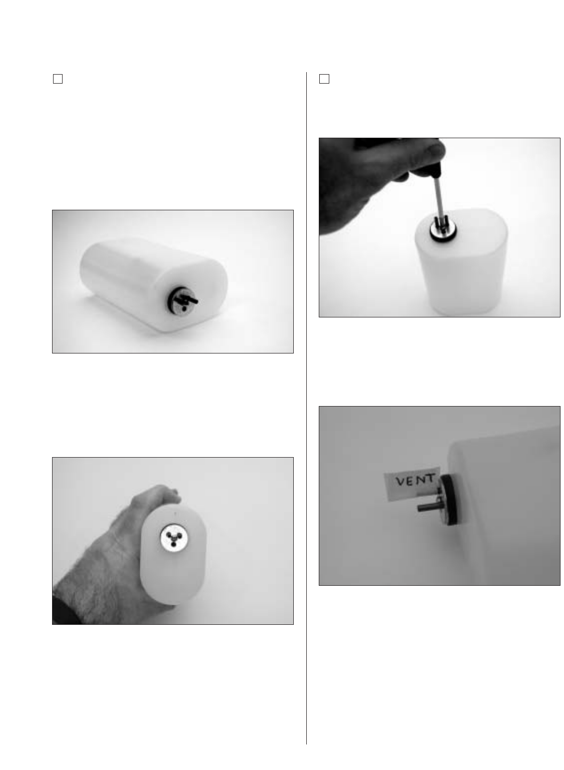
Step 8
Tighten the M3 x 20 screw carefully—do not over tighten.
This allows the rubber stopper to form a seal by being
slightly compressed, thus sealing the fuel tank opening.
Important: Be sure to differentiate between
the vent and fuel pickup tube. Once the tank is
mounted inside the fuselage, it will be difficult
to tell the tubes apart.
Note: The fuel tank will be installed in
a later section.