
Specifications


Table Of Contents
- Table of Contents
- Contents of Kit
- Additional Required Equipment
- Additional Required Tools and Adhesives
- Other Items Needed (not included in the kit)
- Warning
- Before Starting Assembly
- Using the Manual
- Warranty Information
- Section 1: Hinging the Ailerons
- Section 2: Aileron Servo Installation
- Section 3: Aileron Linkages
- Section 4: Hinging the Flaps
- Section 5: Flap Servo Installation
- Section 6: Flap Linkages
- Section 7: Retract Servo Installation
- Section 8: Main Landing Gear and Wheel Doors
- Section 9: Joining the Wing
- Section 10: Mounting the Wing to the Fuselage
- Section 11: Lower Air Intake Installation
- Section 12: Stabilizer Installation
- Section 13: Hinging the Elevators
- Section 14: Hinging the Rudder
- Section 15: Tail Wheel Installation
- Section 16: Fuel Tank Assembly
- Section 17A: Engine Installation
- Section 17B: Engine Installation
- Section 18: Throttle Pushrod and Fuel Tank
- Section 19: Radio Installation
- Section 20: Rudder and Elevator Linkages
- Section 21: Throttle Linkage Installation
- Section 22: Attaching the Cowl
- Section 23: Cockpit Details
- Section 24: Attaching the Canopy
- Section 25: Applying the Decals
- Control Throws and Center of Gravity
- Preflight at the Field
- Adjusting the Engine
- 2003 Official AMA National Model Aircraft Safety Code
54
Section 20: Rudder and Elevator Linkages
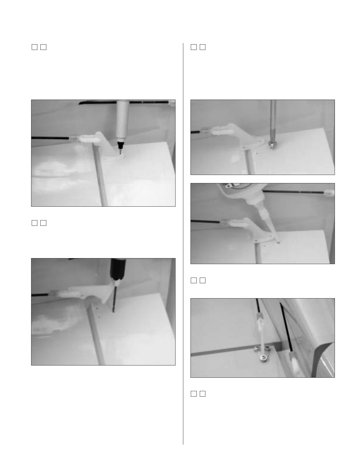
Step 4
Attach the clevis to the control horn. Position the control
horn on the elevator so the control rod is straight, and
the holes in the control horn aligns with the hinge line
of the elevator. Mark the position for the mounting holes
using a felt-tipped pen.
Step 5
Drill three 1/16" holes at the locations marked in the
previous step. The holes only need to be 5/16" deep:
don’t drill through the top of the elevator.
Step 6
Install one of the #2 x 3/8" screws in a hole drilled,
then remove it. Place 2-3 drops of thin CA into the hole
to harden the wood. This will eliminate the potential of
the screw pulling out of the wood. Repeat this for each
of the three holes.
Step 7
Attach the control horn using three #2 x 3/8" screws.
Step 8
Center the elevator servo electronically using the radio
system. Install a servo arm onto one of the elevator
servos. Physically place the elevator control surface
in neutral. Mark the pushrod where it crosses the
holes in the servo arm.