
Specifications


Table Of Contents
- Table of Contents
- Contents of Kit
- Additional Required Equipment
- Additional Required Tools and Adhesives
- Other Items Needed (not included in the kit)
- Warning
- Before Starting Assembly
- Using the Manual
- Warranty Information
- Section 1: Hinging the Ailerons
- Section 2: Aileron Servo Installation
- Section 3: Aileron Linkages
- Section 4: Hinging the Flaps
- Section 5: Flap Servo Installation
- Section 6: Flap Linkages
- Section 7: Retract Servo Installation
- Section 8: Main Landing Gear and Wheel Doors
- Section 9: Joining the Wing
- Section 10: Mounting the Wing to the Fuselage
- Section 11: Lower Air Intake Installation
- Section 12: Stabilizer Installation
- Section 13: Hinging the Elevators
- Section 14: Hinging the Rudder
- Section 15: Tail Wheel Installation
- Section 16: Fuel Tank Assembly
- Section 17A: Engine Installation
- Section 17B: Engine Installation
- Section 18: Throttle Pushrod and Fuel Tank
- Section 19: Radio Installation
- Section 20: Rudder and Elevator Linkages
- Section 21: Throttle Linkage Installation
- Section 22: Attaching the Cowl
- Section 23: Cockpit Details
- Section 24: Attaching the Canopy
- Section 25: Applying the Decals
- Control Throws and Center of Gravity
- Preflight at the Field
- Adjusting the Engine
- 2003 Official AMA National Model Aircraft Safety Code
56
Section 20: Rudder and Elevator Linkages
Step 17
Remove the back plate from the last control horn using
side cutters or a sharp hobby knife.
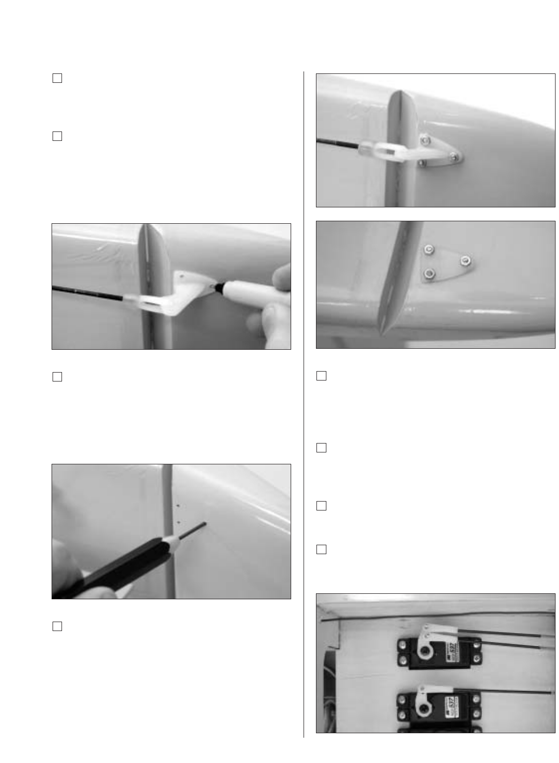
Step 18
Attach the clevis to the control horn. Position the control
horn on the rudder so the control rod is straight, and the
front edge of the control horn aligns with the front edge of
the bevel on the rudder. Mark the position for the
mounting holes using a felt-tipped pen.
Step 19
Drill the locations marked in the last step using a
1/16" drill bit. These three holes will be drilled completely
through the rudder. Take your time, as each hole
must be parallel in order to properly mount the
rudder control horn.
Step 20
Thread three #2 nuts onto the threaded rods. Slide the rod
through the control horn, then through the rudder. Attach
the back plate on the opposite side of the rudder as the
control horn. Finally, thread three nuts onto the rods.
Tighten the nuts, but don’t crush the balsa. Use
threadlocking compound on the nuts to prevent them
from loosening during flight.
Step 21
Physically place the rudder control surface in
neutral. Mark the pushrod where it crosses the holes
in the servo arm.
Step 22
Bend the wire 90 degrees at the mark made in
the previous step
Step 23
Cut the wire 1/2" above the bend.
Step 24
Slide the wire through the outer hole in the rudder control
horn. Secure the wire using a nylon wire keeper.
Photo for Step 20
Photo for Step 20