
Specifications


Table Of Contents
- Table of Contents
- Contents of Kit
- Additional Required Equipment
- Additional Required Tools and Adhesives
- Other Items Needed (not included in the kit)
- Warning
- Before Starting Assembly
- Using the Manual
- Warranty Information
- Section 1: Hinging the Ailerons
- Section 2: Aileron Servo Installation
- Section 3: Aileron Linkages
- Section 4: Hinging the Flaps
- Section 5: Flap Servo Installation
- Section 6: Flap Linkages
- Section 7: Retract Servo Installation
- Section 8: Main Landing Gear and Wheel Doors
- Section 9: Joining the Wing
- Section 10: Mounting the Wing to the Fuselage
- Section 11: Lower Air Intake Installation
- Section 12: Stabilizer Installation
- Section 13: Hinging the Elevators
- Section 14: Hinging the Rudder
- Section 15: Tail Wheel Installation
- Section 16: Fuel Tank Assembly
- Section 17A: Engine Installation
- Section 17B: Engine Installation
- Section 18: Throttle Pushrod and Fuel Tank
- Section 19: Radio Installation
- Section 20: Rudder and Elevator Linkages
- Section 21: Throttle Linkage Installation
- Section 22: Attaching the Cowl
- Section 23: Cockpit Details
- Section 24: Attaching the Canopy
- Section 25: Applying the Decals
- Control Throws and Center of Gravity
- Preflight at the Field
- Adjusting the Engine
- 2003 Official AMA National Model Aircraft Safety Code
Section 2: Aileron Servo Installation
9
Step 4
Place the aileron servo between the mounting blocks and
use a felt-tipped pen to mark the location of the four
servo mounting screws. Note that the servo must not
touch the hatch in order to isolate engine vibration.
Note: Before mounting the servo, it is
suggested to electronically center the servo
using the transmitter, then install the servo
arm to avoid having to remove the servo and
center the arm later. It may be necessary to
slightly trim one of the servo mounting
blocks to clear the servo wire.
Step 5
Remove the servo and use a 1/16" drill bit to predrill
the holes for the servo mounting screws marked in the
previous step. Use the screws supplied with the servo
to mount it to the servo mounting blocks.
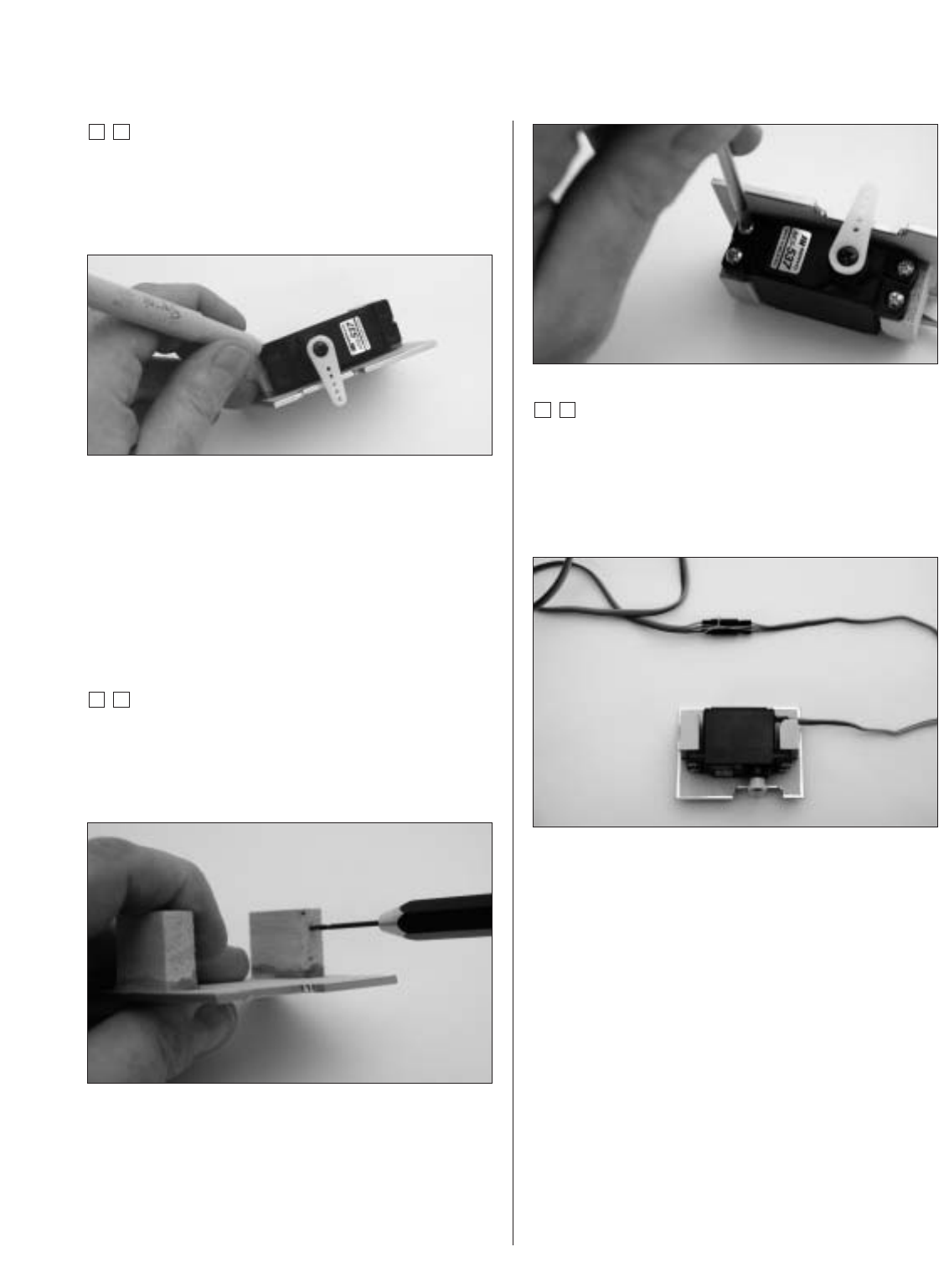
Step 6
Connect a 24" Servo Lead extension (JRPA212) to the
servo lead. Secure the connectors by tying them in a knot
using dental floss (as shown) or by using a commercially
available connector clamp to prevent the servo leads from
becoming disconnected.
Note: It is always a good idea to secure the
servo connector and servo extension together
to prevent the wires from becoming unplugged
inside the wing.
Photo for Step 5