INLINE 4-STROKE ENGINES INSTRUCTION MANUAL FA-100Ti FA-200Ti
Important Before you attempt to operate your [200Ti/100Ti] engine, please be sure to read through these instructions so that you may familiarize yourself with the various parts and other features of the engine. Failure to read and follow these instructions before you proceed to start your engine may result in engine damage and the voiding of your warranty.
Introduction Congratulations on purchasing a SaitoTM 4-stroke engine. When cared for properly, these high-quality, finely crafted engines offer many years of modeling enjoyment. This instruction manual has been developed to ensure optimum performance from the Saito engine you purchased. The instructions must be read through completely and understood thoroughly prior to mounting and running the engine.
Mounting the Engine Sturdy engine mounting is required. Mounting beams should be integral to the airframe and should provide sufficient support as necessary to absorb vibration. A beam style motor mount (SAI200Ti/100Ti-95) is provided with the FA-200Ti/100Ti to ease mounting the engine to the firewall. Engine installation should be made so that periodic maintenance can be performed easily, to include the checking and adjustment of valve clearances. 1.
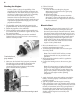
Carburetor Fuel The carburetor is located on the right side of the engine as shown in the photo below. The FA-200Ti/100Ti does not utilize a choke device, as the engine draw is sufficient for priming by putting your fingers over the muffler exhaust openings and turning the propeller over several times (without the glow driver(s) attached). For maximum protection and longevity of Saito engines, Saito recommends a high-quality fuel containing 10-15% nitro methane, such as Hangar 9® Aero-Blend, Omega.
Starting the Engine Caution: There is always the possibility of the propeller flying off if the propeller nut loosens due to detonation or "kick-back" when the engine is run too lean or is under a heavy load. This is especially true of four-stroke engines and can be very hazardous. Saito has provided a prop nut/antiloosing nut with the engine and they should be used to prevent the propeller from flying off, even if the propeller should loosen. 1.
8. Disconnect the glow plugs from the engine. Close the high-speed needle valve slowly until the engine rpm's increase. Adjust the high-speed needle valve slowly, in small increments. The use of a tachometer is highly recommended to prevent the over-revving of the engine during the initial start-up and break-in process. Caution: Do not exceed 4,000 rpm for the first 10 minutes of operation. This allows the parts to mate properly under good lubrication (rich).
5. Repeat the procedure of alternatively running the engine fast then slow by varying the needle valve position. Gradually increase the short periods of maximum rpm (do not exceed 4,500) running until one full tank of fuel has been consumed in this manner. Caution: Do not lean out the fuel mixture at this stage. This could result in the seizure of the engine. 6. After the engine has been run-in on the ground, flights in the air should be at a moderately rich setting.
Valve/Rocker Arm Gap Adjustment The valve clearance has been correctly set at the Saito factory. Usually you will not have to make adjustments until after several hours of normal operation. If you experience a loss of power, of if the engine has been disassembled due to a crash or repairs, the valve clearances should be checked and readjusted as necessary.
Troubleshooting Tachometer SYMPTOM CAUSE CORRECTIVE ACTION Engine fails to start Low voltage on starting battery Replace/recharge the starting battery Bad glow plug(s) Inspect/replace bad glow plug(s) Insufficent priming Repeat priming procedure "Flooded" due to excussive priming Disconnect battery, remove glow plugs, and rotate the propeller several times to "clear" each cylinder Engine fires but does not run Over primed Disconnect battery and rotate the propeller several times to "clea
Callout Description Part No. Callout Description Part No.
Side and Top View with Dimension Chart A-73 37 B2-45 51 32.90 cc 28.2x2 mm 26.4x2 mm 1460 grams 8x1.25 mm AAC 16.5ccx2 3 16x8-18x10 2,000-9,200 B1-30 Engine Specification H-105 Displacement: Bore: Stroke: Weight: K(ISO): Cylinder: Horsepower: Propeller: Practical Range(rpm): D-86 4-4.2ø 15˚ Outside Dimensions(mm) A B B1 B2 : 73 : 62 : 30 : 45 C D E F1 INLINE ENGINE DATA Disp Items (cc) FA-200Ti 33 : 160 : 86 : 88 : 71.5 F2 F3 G H : 37 : 51.
FA-100Ti CHART Callout Description Part No. Callout Description Part No.
Side and Top View with Dimension Chart D-76 4-4.2ø A-64 Engine Specification 17.97 cc 24.80x2 mm 18.60x2 mm 1,100 grams 8x1.25 mm AAC 8.98ccx2 1.5 14x6-15x6 2,000-10,000 H-90 Displacement: Bore: Stroke: Weight: K(ISO): Cylinder: Horsepower: Propeller: Practical Range(rpm): Outside Dimensions(mm) : 64 : 56 : 27 : 53 C D E F1 INLINE ENGINE DATA Disp Items (cc) FA-100Ti 18 : 152 : 76 : 93 : 61 F2 F3 G H : 39 : 52 : 102 : 90 17.5˚ 17.
Consumer Warranty and Repair Policy Warranty Repairs SaitoTM engines are guaranteed against workmanship and manufacturing defects for a period of 3 years from the original date of purchase. This warranty is limited to the original purchaser of the engine and is not transferable. Warranty repairs will not cover: To receive warranty service, you must include your original dated sales receipt to verify your proof-ofpurchase date.
Consumer Warranty Registration Fill in and mail this form along with your dated sales receipt (send copy, keep original for your files) within 10 days of purchase to: Horizon Service Center Attn: Saito Warranty Dept. 4105 Fieldstone Road Champaign.
SAITO Distributred exclusively by Horizon Hobby, Inc., Champaign, IL 61822 www.horizonhobby.