Preface Thank you for choosing SAJ solar inverter. We are happy to provide you with first-class products and quality service. The manual includes installation, operation, maintenance, troubleshooting, and safety notice. As long as you follow the instruction of this manual, you will get the professional guidance and our wholehearted service. Customer-orientation is our forever commitment. We hope this “User Manual” become your good helper in solar power generation. Please check the latest version at www.
User Manual Contents 1. Information on this Manual...........................................................................................................................................1 1.1 Validity..............................................................................................................................................................................1 1.2 Target Group....................................................................................................................
User Manual 1.Information on this Manual 1.1 Validity This User Manual describes instructions and detailed procedures for installing, operating, maintaining, and troubleshooting of the following SAJ grid-tie inverters: Suntrio-TL6K, Suntrio-TL8K, Suntrio-TL10K, Suntrio-TL12K Suntrio-TL15K, Suntrio-TL17K, Suntrio-TL20K Please keep this manual where it will be accessible at all times. 1.
User Manual 2.Safety 2.1 Intended Use The Suntrio-TL series inverters are PV inverter which converter the direct current of a PV array into alternating current and feed this into the electricity grid. The inverters are designed according to the safety rules. However, improper use, alteration or modification may cause lethal hazards for the operator or third parties, or may result in damage to the units and other property. SAJ is not responsible for the loss and invalidate these warranty claims. Figure 2.
User Manual WARNING ● The installation, service, recycling and disposal of the inverters must be performed by qualified personnel only in compliance with national and local standards and regulations. ● Any unauthorized actions including modification of product functionality of any form may cause lethal hazard to the operator, third parties, the units or their property. SAJ is not responsible for the loss and deny these warranty claims. ● Suntrio inverters must only be operated with PV generator.
User Manual 3.Product Overview 3.1 Product Appearance Figure 3.1 Suntrio inverters Overview 3.2 Major Characteristics SAJ Suntrio inverter has following characteristics which make SAJ grid-tied solar inverter “Higher Efficiency, High Reliability and Lower Cost”. Leading technology • Max. efficiency 98.1% • MPPT accuracy up to 99.
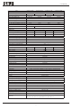
User Manual 3.3 Technical Data Type Input (DC) Max. DC Power [W] Max. DC Voltage [V] MPPT Voltage Range [V] Nominal DC Voltage Start Voltage[V] Min. DC Voltage[V] Max. DC input Current PV1 / PV2 [A] Number of MPPT String(s) per MPPT DC Switch Output (AC) Rated AC Power [W](@230V,50Hz) Max. AC Apparent Power [VA] Rated AC Current[A] Max. AC Current [A] Nominal AC voltage/ range Grid frequency/ range Total Harmonic Distortion (THDi) Power factor, adjustable Feed-in Phase / Connection Phase Efficiency Max.
User Manual Type Input (DC) Max. DC Power [W] Max. DC Voltage [V] MPPT Voltage Range [V] Nominal DC Voltage Start DC Voltage[V] Minimum DC Voltage[V] Max. DC input Current PV1 / PV2 [A] Number of MPPT String(s) per MPPT DC Switch Output (AC) Rated AC Power [W](@230V,50Hz) Max. AC Apparent Power [VA] Rated AC Current[A] Max. AC Current [A] Nominal AC voltage/ range Grid frequency/ range Total Harmonic Distortion [THDi] Power factor, adjustable Feed-in Phase / Connection Phase Efficiency Max.
User Manual 4.Installation Instructions 4.1Unpacking Check the delivery for completeness and for any visible external damage. Contact your specialist dealer if anything is damaged or missing. A B C D F G H I E Figure 4.
User Manual 4.2 Mounting Instructions Figure 4.2 Mounting Instructions Mounting on a solid surface out door or indoor. ● Site altitude is less than 2,000m above the sea level. ● The mounting location must be clear and safely accessible at all times without the use of additional aids such as scaffolding or lifting platforms. If this is not the case, service work may be restricted. ● Mount vertically or tilted backwards by max. 15° ● The connection area must point downwards.
User Manual Figure 4.3 Safety Clearance of Single Inverter ●Multiple inverters are mounted in an area,the below clearances between the inverters are recommended.This ensure the flow of the air inlet and air outlet openings and optimize heat dissipation. Figure 4.
User Manual 4.3 Mounting Procedure 1) Use the rear panel in the package as a drilling template and drill 7 holes with 8mm diameter and depth in 50mm, as illustrated below, (Units: mm) Figure 4.5 Holes Position 2) Fix the rear panel on the wall with the expansion tubes and expansion screw. Figure 4.
User Manual 3) Hang the inverter on the rear panel, and check whether the pothook is installed in place. If there are any errors, remove the inverter, reinstall, as shown below. Figure 4.7 Mounting the Inverter 4) After Confirming the inverter is installed well, tight the inverter with M4 Phillips pan head screws. Figure 4.8 Secure the Inverter 5)Please carefully check the accessories and original carton to make sure during the installation every necessary part is used and nothing is missed.
User Manual 4.4 Optional Anti-Theft Protection To protect the inverter from theft, you can lock inverter with a padlock. The padlock must meet the following requirements: Size: A:6 mm – 8 mm diameter B:23mm – 29 mm C:23mm – 28 mm D:39mm – 50 mm E:13mm – 18 mm Figure 4.9 Padlock for Anti-theft Protection Installation of the padlock Put the shackle of the padlock through the hole and close the padlock, as following picture. Figure 4.
User Manual 5.Electrical Connection 5.1 Safety . NOTICE ●Internal components of the inverter can be damaged by Electrical discharge, take measurement to avoid Electrical discharge during relevant operation. ●Earth yourself before touching any components. 5.2 Overview of Connection Area A B C D F Figure 5.
User Manual A B C D F Figure 5.2 Connection Area Overview of Suntrio-TL15K/17K/20K Object Description A DC input terminals (PV1 and PV2) B DC switch (optional) C EXT port D Ethernet RJ45 interface E AC cover terminal F RS485 interface G Grounding terminal Table 5.
User Manual 5.3 Connection Cables Requirements The user can select connection cable according the table below. DC Side AC Side cross section (cu) Mini cross section (cu) Suntrio-TL6K/8K 4mm2 / 6mm2 4mm2 Suntrio-TL10K/12K 4mm2 / 6mm2 4mm2 Suntrio-TL15K 4mm2 / 6mm2 6mm2 Suntrio-TL17K 4mm2 / 6mm2 6mm2 Suntrio-TL20K 4mm2 / 6mm2 6mm2 Model Table 5.
User Manual 5.4 Miniature circuit breaker DANGER When more than one inverter is connected in parallel to the same miniature circuit-breaker, the protective unction of the miniature circuit-breaker is no longer guaranteed. This could result in a cable fire or destruction of the inverter. ●Never connect several inverters to a single miniature circuit-breaker.
User Manual 5.5 Connecting the Electricity Grid (AC) 5.5.1Conditions for the AC Connection You must comply with the connection requirements of your network operator. Residual Current monitoring The inverter is equipped with an integrated all-pole-sensitive residual-current monitoring unit. The inverter can automatically differentiate between residual currents and normal leading leakage currents.
User Manual 2)Please insert the striped cable into bootlace ferrule and crimp the contact. 3)Screw off the AC cover and insert the 5 wires into AC cover assembly with the following sequence. 4)Release the five screws at the cable terminal. Then route the 5 wires into the cable terminal according to the marks on the front case while L1(R), L2(S), L3(T) represent 3 Live line, N represent Neutral line and PE is ground. NOTE: • The PE conductor must be 5 mm longer than the L and N conductor.
User Manual 5)Screw the cap nut of the cable tightly. 5.5.3 Connecting the Second Protective Conductor If required by the installation, the earth terminal can be used to connect a second protective conductor or as equipotential bonding. Procedure Take out parts from the packing and insert the earthing wire to “PE” terminal located at the right of the inverter, then tighten the screw.
User Manual 5.6 Connecting the PV Array (DC) 5.6.1 Conditions for DC Connection NOTE: Suntrio-TL6K/8K/10K/12K: Dual MPPT(PV1 and PV2), two DC input connection sets per MPPT. Suntrio-TL15K/17K/20K: Dual MPPT(PV1 and PV2), three DC input connection sets per MPPT. ● For input area PV1 or PV2, The PV modules must meet the following requirements: Same type Same number of in-series-connected PV modules Identical direction Identical tilt The open circuit voltage of each string should never exceed 1000VDC.
User Manual 5.6.2 Connection Procedures by H4: Connect the PV generator and the inverter using H4 connectors, as follows. Note: If using MC4 connector, the operating procedures are similar to that of H4 connector. The DC connectors come pre-assembled and the caps are loose. The whole connector will include the male side and female side as showed below: Male side connector (M) Female side connector (F) Assembly Instructions: 1)Strip the cable with the length of 0.
User Manual 3)Insert stripped cable into contact barrel and insure all conductor strands are captured in the contact barrel and the conductors are visible in the contact barrel observation hole. Barrel observation hole Conductor should be visible Barrel observation hole Conductor should be visible 4)Crimp contact barrel by using the hex crimping die. Ensure it is fixed. Crimped socket contact Cable Requirements Cable Size Cable pull – out force requirement 4 mm² Min. 400 N.m(90Lbs) 6 mm² Min.450N.
User Manual 6)Wrest the cap by using the torque of 2.6~2.9N·m. 7)After wrested the cap tightly, align the 2 half connectors and mate them together by hand until a “click” is heard or felt. 8)Connect the positive and negative terminals from the PV panels to positive and negative terminals on the PV inverter. Note: In order to seal the inverter, all DC inputs that are not required have to be closed.
User Manual 5.7 Communication and Monitoring Setting SAJ offers 2 standard communication interfaces for Suntrio-TL series solar inverters: RS485 and Ethernet RJ45. All the SAJ products involved in the solar monitoring system are: SAJ Logger: data logger for local monitoring and maintenance of large solar power plants. SAJ Web Portal: free monitoring application through web, IPhone, IPAD and Android App.
User Manual PC+SAJ Logger Multi-point Monitoring Figure 5.20 PC+SAJ Logger Multipoint Monitoring Connection Procedures 1)Inverter 1 connects to Inverter 2 through RS485 cable; Inverter 2 connects to Inverter 3 through RS485 cable. In the same way to connect all inverters. 2)Inverter 1 connects to SAJ Logger through RS485-L cable. 3)Connect SAJ Logger to PC through Router. 4)Open the internal Web Server of SAJ Logger for plant and inverter monitoring.
User Manual 5.7.2 Communication through Ethernet RJ45 When users choose Ethernet communication solution, users can access to Inverter real-time information through Inverter IP address, or through SAJ Logger IP address. The configuration is shown in Figure 5.21 as below: Figure 5.21 Communications through Ethernet RJ45 5.7.
User Manual 5.7.4 Communication Cable Assembly InstructionsAll cables All cables mentioned in this mentioned in this Manual are 5E Shielded Cable, as shown in Figure 5.22. Figure 5.22 5E Shielded Cable Terminals: According to different communication solutions, users may need at least one of the below terminals. They are 3Pin Connector and RJ45 Plug as shown in Figure 5.23 and Figure 5.24 Figure 5.
User Manual Figure 5.24 RJ45 Plug and Pin Number Tools When making a communication cable, the professional tools shown in Figure 5.25 below are needed. Figure 5.25 Tools for Making a Communication Cable RS485 Cable When using RS485 for monitoring, users need RS485 cables to connect between inverters for multi-point monitoring. In this case, we provide connection by using the 3Pin connectors as shown in Figure 5.23. Each cable should be connected to the connectors according to below Table 5.
User Manual RS485-L Cable RS485-L cable is used to connect Inverter and SAJ Logger when inverters are monitored via RS485. One end of the cable uses 3Pin Connector, and the other end uses RJ45 Plug. Connection is shown in Table 5.5 as below: Wire Blue & White Blue Connector No. 1 2 RJ45 plug's Pin NO 5 4 Table 5.5 RS485-L Cable Assembly Order RJ45 Cable RJ45 cable is the standard cable for Ethernet communication.
User Manual 6. LCD Operation 6.1 LCD Display Overview Figure 6.1 Inverter HMI (Human Machine Interface) Object Description Power status indicator Yellow light on: Inverter power systerm normal A Inverter status indicator: Flashing red light: Inverter faulty status. Green light on: Inverter normal status. Red light and Green light are both off: inverter initialization status or inverter counting down to connect to grid. B Communication status indicator: Flashing blue light: receiving data.
User Manual 6.2 Startup the Inverter Suntrio inverter can be configured for various countries, if it is the first time the inverter starts up after installation, LCD will quickly switch to and stay at the country setting interface. Only the inverter is set to comply with a certain country, it will work and display normally. Otherwise, LCD will always stay at the “Please Set The country First” interface.
User Manual Figure 6.2 Connect to the Gird Countdown 6.3 LCD Main Screen When inverter countdown finishes and starts to connect to grid, LCD will display the main screen as below. The main screen consists of menu bar, main display area, auxiliary display area, status bar (including inverter status, description of main display area, data and time). Please refer to Table 6.2 for inverter status description, Table 6.3 for auxiliary display area items description.
User Manual 6.4 LCD Menu Structure Menu structure is shown as Figure 6.4.Menu can be selected by pressing the ‘▲’, ‘▼’, ‘ ’, ‘ ’ and confirmed by pressing ‘Enter’, then LCD main display area will display the information accrodingly.
User Manual 6.4.1 LCD Graph Submenu Graph submenu consists of E-Today, E-Month, E-Year and E-Total. LCD main display area will display the corresponding information after confirming the Graph submenu by pressing ‘Enter’. The Figure 6.5 below is the E-Month Screen.please refer to the Table 6.4 for E-Today, E-Month, E-Year and E-Total display information explanation. Figure 6.
User Manual 6.4.2 LCD Setting Submenu Setting submenu includes the below setting of the inverter: Ethernet: Figure 6.6 is the Ethernet setting screen.Either the IP address is set to be obtained auto or manually, the IP address displayed on the screen is the current IP address of the inverter. The focus can be moved by pressing the ‘ ’, ‘ ’, and IP address/IP address obtain method can be changed by pressing the ‘▲’, ‘▼’. The change will be saved by pressing ‘Enter’.
User Manual Figure 6.7 Inverter Embedded Web Server Screen Language & Time: Move the focus to the setting item by using ‘ ’, ‘ ’ , and the setting can be changed by pressing ‘▲’, ‘▼’. The setting will be saved by moving the focus to ‘OK’ and press ‘Enter’. Figure 6.
User Manual Grid Compliance:(only for SAJ or SAJ representative) Different country has different grid connection standard for inverter. The grid compliance of the inverter can be changed by this setting menu when the inverter is run for the first time or the country selection is wrong. Enter the Grid Compliance submenu and confirm the password, then the country which the inverter installed in can be selected. After the selection, press ‘ ’ to move the focus to button ‘OK’, then press ‘Enter’.
User Manual Figure 6.10 Clear Energy Operation Screen. LCD Setting: LCD setting includes: LCD backlight brightness and LCD backlight Time-out, as shown in Figure 6.11.Press ‘ ’, ‘ ’to move the focus and press ‘▲’, ‘▼’ to change the value. After the change, move the focus to button ‘OK’ and press ‘Enter’. Figure 6.
User Manual Factory Reset: (only for SAJ or SAJ representative) The user will set inverter to factory setting and delete all data saved in the inverter, for example, Error Records and Energy. The operation requires a password. After inputting the password, move the focus to button ‘OK’, and press ‘Ent er’. Figure 6.12 Factory Reset Screen Change Password (only for SAJ or SAJ representative) SAJ or SAJ representative can change the passwords for ‘Grid Compliance’ and ‘Factory Setting’.
User Manual ■Run-Info AC-Parameters: Inverter AC output data can be viewed in the menu, as shown in Figure 6.14 . Figure 6.14 AC Parameters Screen DC-Parameters: DC data can be viewed in this screen, as shown in Figure 6.15. Figure 6.
User Manual Error-Records: Inverter error record can be viewed in this menu, as shown in Figure 6.16. The screen can be scrolled by pressing ‘▲’, ‘▼’. Error record can be flipped over to another one by moving the cursor to button ‘Previous’ or ‘Next’ and press ‘Enter’. Please refer to chapter eight for error description and guidance. Figure 6.16 Error Records About When the focus is moved to “About”, press “Enter” to enter the “About Screen”, as shown in Figure 6.17. Please refer to Table 6.
User Manual Item Descripiton InverterType Inverter Model Inverter SN: Inverter Serial Number Inverter PC Inverter Product Code HMI SW: Human Machine Interface Software Version Master Ctrl. SW (Control Board Master MCU Software Version) Slave Ctrl. SW (Control Board Slave MCU Software Version) Portal ID Portal ID. The Portal account ID for Web portal registration: http://webportal.saj-solar. com.
User Manual 7.Recycling and Disposal To comply with European Directive 2002/96/EC on waste Electrical and Electronic Equipment and its implementation as national law, electrical equipment that has reached the end of its life must be collected separately and returned to an approved recycling facility. Any inverter that you no longer required must be returned to your dealer or you must find an approved collection and recycling facility in your area.
User Manual 8.Troubleshooting Error Code LCD Display Message Phenomenon and Possible Cause Phenomenon and Possible Cause 1)A fault has occurred in the Relay(Suntrio Series have 8 relays at 1 Relay Error M the AC side of the inverter) when the If this error occurs often, please inverter detects itself during start-up. contact local agent or SAJ 2)The Grid voltage at both sid e s Service line. of the relays is interfered when the relays switch on and off.
User Manual Error Code LCD Display Message 15 L1 Volt 10Min High M 16 L2 Volt 10Min High M 17 L3 Volt 10Min High M 18 L1 Freq High M 19 L1 Freq Low 20 L2 Freq High M 21 L2 Freq Low 22 L3 Freq High M 23 L3 Freq Low 24 L1 No Grid Err M 25 L2 No Grid Err M 26 L3 No Grid Err M Phenomenon and Possible Cause Phenomenon and Possible Cause Average of output voltage out of range. Check the Grid Compliance of M 1)The local Grid Frequency is beyond the permitted range.
User Manual Error Code LCD Display Message Phenomenon and Possible Cause Phenomenon and Possible Cause 1)The Voltage of the BUS middle point is beyond half of the BUS voltage. 32 Bus Volt Bal.Err M 2)If random, a possible cause is the quick If the error is still active, please contact the local agent or SAJ Service line. variation of grid voltage. 1)The open-circuit voltage of the PV 33 Bus Volt High M generator is higher than the maximum DC input voltage of the inverter. 2)Sudden DC surge.
User Manual Error Code LCD Display Message 49 Reserved(bit 52) M 50 Lost Com.
User Manual Error Code LCD Display Message 73 L1 No Grid Err S 74 L2 No Grid Err S 75 L3 No Grid Err S 76 PV1 Volt High S Phenomenon and Possible Cause Check the AC connection. The connection between Grid and If everything is correct, inverter has problems or is missing. you need to contact local agent or SAJ Service line. 1)The open-circuit voltage of the PV generator is higher than the maximum DC input voltage of the inverter. 2)Sudden DC surge. 77 PV2 Volt High S 78 PV1 Curr.
User Manual 9.Guaranty Service Please refer to the warranty card. 10.Contact SAJ If you have technical problems concerning our products, contact the SAJ Service line. Technical Support & Service: International Service & Technical Support Addr: No.17, Xiangshan Road Guangzhou Science City,Guangdong,R.China. Tel: +86 20 6660 0082 Fax: +86 20 6660 8589 E-mail: service@saj-solar.com SAJ Europe Service Center Addr: Maagdenstraat 44, 9600 Ronse, Belgium Tel: +32 484 945 445 E-mail: service.europe@saj-solar.