HIGH INTENSITY DISCHARGE (HID) LAMP INSTALL P/N: 10-8002-C11670C Saleen Performance, Inc. 76 Fairbanks Irvine, CA 92618 949-597-4900 www.saleen.
IF YOU ARE NOT EXPERIENCED IN THE AREA OF AUTOMOTIVE MECHANICS, WE STRONGLY URGE THAT YOU REFER THIS INSTALLATION TO A CERTIFIED INSTALLER OR TECHNICIAN 2
Saleen Speedlab High Intensity Discharge (HID) Headlamp Kit Installation Guide for 2005 Mustang Thank you for buying the Saleen High Intensity Discharge (HID) Headlamp Kit for the 2005 Mustang. We appreciate your business, and we hope you enjoy your product. For your benefit, please read the following instructions completely and thoroughly before attempting to install the HID kit.
Function: I Remove the front fascia II Remove shroud III Stock Headlamps Removal IV Ballast Install V Install HID harness VI Headlamp alignment Page 5-7 8 9 10-12 13-16 17 Obtain the following tools • ¼” drive ratchet • ¼” drive 5.
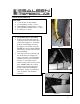
I Front Fascia Removal Tools need: • ¼” air ratchet, or drive ratchet • 5.5 mm shallow socket, ¼” drive • Short Phillips #2 head socket, ¼” drive • 10 mm shallow wobbly socket, ¼” drive • 8” extension, ¼” drive 1. Keep all hardware you remove. 2. Starting on the left side of the car remove the three screws from each wheel well using the ¼” air ratchet with the short Phillips #2 socket. See figure 1 for location of screws.
4. Underneath the front fascia (Figure 4), there are four screws that need to be removed. Use the ¼” drive air ratchet with a 5.5 mm shallow socket. 5. Remove the bolt shown in Figure 5. There are two of these bolts. Use the ¼” drive air ratchet with a 10 mm shallow wobbly socket. 6. Repeat steps 1 and 2 on the right side of the car. 7. Remove the fascia by placing the palm of your hand (see Figure 6 for location) and push down until the fascia loosens. See Figure 3.
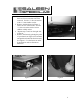
8. Disconnected the running lights, fog lights, and side markers. Figure 7 is the fog light connector and Figure 8 shows both the turn signal and side marker. Figure 9 shows a close up of the running light/turn signal connector. Let the connectors hang until the fascia is ready to be reinstalled.
II Remove Shroud Tools needed: • Panel puller 1. Remove 6 pushpins. Make sure to keep the pushpins because they will be reused when reinstalling the shroud.
III Stock Headlamp Removal Tools needed: • Air ratchet or drive ratchet, ¼” drive • 10 mm shallow socket, ¼” drive • 8” extension, ¼” drive • Foam tape 1. Tape off the corners of the bodywork so it doesn’t scratch the lens during installation. Leave tape on until new headlamps are fastened. 2. Remove three screws, 1 on the top and 2 on the bottom (Figure 1) of the stock headlampusing a 10 mm shallow socket with a ¼” air ratchet or drive ratchet. See figure 2 & 3 for a close up.
IV Ballast Installation Tools needed • ¼ ” drive 1/8” Alan socket • ¼” drive 3/8” deep socket • ¼” drive 10 mm shallow socket • 8” Extension, ¼” drive • ¼” drive ratchet • Panel puller • Drill • Drill bit ¼” • Drill bit 1/8” Part Number 00-9011-C11360* 00-9003-C11359* 06-1202-C11361A 06-1202-C11362A Descriptions SCREW, BUTTON HD SOCKET CAP SCREW, 18-8 SS, 10-32X1.25" LOCKNUT, NYLON 18-8 SS, 10-32 SPACER, BALLAST 1/2" PLASTIC SPACER, BALLAST .75" PLASTIC Qty 5 5 2 3 1. Remove the fender liners.
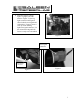
2. From the wheel well drill holes to mount the ballast. Disconnect the ballast from the headlamp and use it as a template. Figure 4 shows the passenger side of the car. The critical hole is labeled in Figure 4. When marking the other two holes makes sure the ballast is level before marking your holes.
3. Remove the cover that is attached to the ballast. It sets flush against the fender wall to prevent any rattling. Align the spacers in the proper locations (P/N 00-1202-C11362*, and 00-1202-C11361*) then fasten the ballast down using part numbers 009003-C11359*, and 00-9011-C11360*. Figure 5 shows the ballast in the proper location. Figure 6 shows the mounting locations for the hardware. Make sure the locknut is facing the headlamp. If it is reversed the screw will push against the fender liner. 4.
V HID Wire Harness Installation Tools needed: • Panel puller • ¼” drive ratchet • ¼” drive 10 mm deep socket • ¼” drive 8 mm socket • ¼” drive 1/8” Alan tool • ¼” drive 3/8” deep socket • ¼” drive 8” extension Part Number 06-1202-C11319A 06-1202-C09903A 06-1202-C09904A 00-9001-C07636* 069-700 069-310 Descriptions HARNESS, HID 2005 MUISTANG HEADLIGHT, BI-FUNCTION HID 5 3/4" RH KIT HEADLIGHT, BI-FUNCTION HID 5 3/4" LH KIT CAPSCRW BUT HD M6x1x16mm SS 4” Zip tie SCREW PAN HD PHIL SELF DRIL 410 SS #8-18x1/2" Q
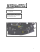
1. Figure 1 is an overview of the routing of the wire harness. 2. The ground and the positive lead are at one end of the harness. The positive lead (red wire with ring terminal) gets attached to the fuse box (Figure 2). Figure 3 shows a close up. Use a ¼” drive ratchet with a 10 mm socket and install the ring terminal. 3. The ground (black wire with ring terminal) will be connected next to the fuse box. Use the 10 mm socket with, ¼ drive with an 8” extension to fasten the ring terminal down. See figure 4.
4. Use an existing screw in the body (Figure 5a) to fasten the relays. Use the 10 mm socket with the 8” extension to remove the screw. A new screw will be used to fasten down the relays. Connect the relay housing by the, inter locking system then unplug the circuits. Fasten down the relay housing using P/N 009001-C07636*, and then reconnect the relay. 5. Figure 5b shows the fuses. Use P/N 069-310 to attach the fuses. First make a pilot using a 1/8” drill bit. Line up the fuses and fasten them down. 6.
8. Plug #2 (Figure 6) comes off the new wire harness and attaches to the ballast, and plug #5 (Figure 8) comes off the headlamp and attaches to the ballast. Both passenger and driver sides are the same. 9. Plug #3 (Figure 7) comes from the wire harness and plug #4 (Figure 8) comes from the back of the headlamp. These two are attached on both the driver and passenger sides. 10. Plug #1 (Figure 7) comes from the new wire harness and attaches to the stock connector that was attached to the original headlamp.
VI Headlamp Alignment Tools needed • Phillips head screw driver 10” long shaft 1. Park the vehicle 25ft from a flat white aiming wall on a flat level surface. 2. Ensure the wall makes a 90-degree angle with the floor and the car is facing the wall. 3. Measure the vertical distance from ground to the center of the HID bulb. 4. Mark a horizontal line on the aiming wall at the same height as the center of the bulb (Figure 2). 5.