SALEEN SERIES VI.5 S/C HIGH FLOW LID UPGRADE INSTALLATION MANUAL: Mustang GT / Saleen 281 / Saleen 302 2005 to 2010 Model Year P/N: 10-8001-C19588A Saleen Performance Vehicles 1-800-888-8945 www.saleen.
STOP IF YOU ARE NOT EXPERIENCED IN THE AREA OF AUTOMOTIVE MECHANICS, WE STRONGLY URGE THAT YOU REFER THIS INSTALLATION TO A CERTIFIED INSTALLER OR TECHNICIAN. ENSURE THE VEHICLE PARKING BRAKE IS ON AND THE TRANSMISSION IS IN PARK OR IN GEAR WHEN WORKING ON IT.
Installation Guide High Flow Supercharger Lid for Series VI & VI.5 Superchargers 2005 to 2010 Models WELCOME! Thank you for buying the Saleen High Flow supercharger lid for the Series VI and VI.5 Supercharger kits. This lid is compatible with all model years the Series VI & VI.5 kits were available. The High Flow lid is also compatible with the Saleen cold air kit. The Saleen High Flow lid is designed in such a way that it eliminates obstructions in the intake track that plagued the previous lid design.
Pre-Installation Precautions: To help ensure the proper operation of your vehicle, follow the guidelines below: IF YOU ARE NOT EXPERIENCED in the area of automotive mechanics, we strongly urge that you refer this installation to a certified installer or technician. STOP PAY ATTENTION TO VEHICLE TYPE NOTATION because there are installation steps in this manual that differ based on whether your vehicle is a 2005 to 2009 model or a 2010 model*.
Table of Contents A Strut Tower Brace Equipped Vehicles B 2005 to 2009 Models C 2010 Models I. Introduction Pg. I II. Precautions (PLEASE READ CAREFULLY) Pg. II II. Table of Contents Pg. III III. Requirements Pg. IV Parts List IV. Tear-Down Instructions Battery Disconnection A Strut Tower Brace Removal B Intake Snorkel Removal (2005 to 2009 Models) C Intake Snorkel Removal (2010 Models) Throttle Body Removal EVAP & Fuel System Disconnection Supercharger Lid Removal Fuel Rail Removal Pg. 1 Pg.
PARTS INCLUDED IN HIGH FLOW S/C LID KIT 10-1607-B19560 06-1607-C09882 06-1607-B19559 00-9304-C19185 00-1607-C19548 06-1607-C18446 00-1607-C19550 00-1607-C19549 00-1607-C19547 00-1607-C19551 00-1607-C18833 00-9001-C18850 00-9001-C18849 06-1607-C18834 00-1702-C145400 TBD 00-9004-C002270 00-2003-C104480 08-1704-B15501 00-1703-C070820 00-1704-C092600 00-1704-C153070 SERIES 6.5 SUPERCHARGER HIGH FLOW LID UPGRADE GASKET, INLET TUBE '05 MUSTANG INLET SNORKEL, SERIES 6.
TORQUE ITEM OPERATION 2010 MODEL SHOWN - 2005 TO 2009 TYPICAL NOTICE: No smoking, flames, or sparks around the battery. Batteries can give off fumes that are flammable and may ignite if there is any form of spark or open flame near it. 10 10 ITEM Remove the red boot, and disconnect battery positive terminal from the battery with an 8mm socket. PART NUMBER QTY.
TORQUE ITEM OPERATION 10 Remove the four 13mm nuts (two per strut tower brace bracket), and lift each bracket off of the strut tower. 20 NOTICE: PICTURE 10 is from a vehicle equipped with the Saleen N2 Adjustable Suspension (P/N: 06-1300-A19349). If the vehicle is equipped with this suspension, the upper strut mount nuts will be 12mm. 10 20 Disconnect one of the strut tower bar brackets from the bar. The bracket is attached with an Allen head bolt and a 17mm nut.
TORQUE ITEM OPERATION 10 10 Pull the red tab on the top of the MAF connector away from the air box lid to un-lock the connector. Depress the tab on the top of the connector, and disconnect. 20 Disconnect the crankcase vent tube from the snorkel (just forward of the throttle body). Push on the green locking tab, and pull the vent tube away from the snorkel. 30 With a flat blade screwdriver, loosen the clamp that secures the air box snorkel to the throttle body.
TORQUE ITEM OPERATION 10 20 30 Pull the red tab on the top of the MAF connector away from the air box lid to un-lock the connector. Depress the tab on the top of the connector, and disconnect. Disconnect the crankcase vent tube from the snorkel (just forward of the throttle body). Push on the green locking tab, and pull the vent tube away from the snorkel. 30 With a flat blade screwdriver, loosen the clamp that secures the air box snorkel to the throttle body.
TORQUE ITEM OPERATION 20 10 Disconnect the throttle position sensor electrical connector by sliding the red shield on the connector towards the front of the car. Push down on the now exposed tab, and pull the connector towards the front of the vehicle to remove. 20 Disconnect the electronic throttle control electrical connector by pulling the red locking tab outward. Pull the connector outward. 30 Remove the four 10mm bolts securing the throttle body. Remove the throttle body.
TORQUE ITEM OPERATION 1 OF 8 SHOWN NOTICE: No smoking, flames, or sparks around the fuel system. The fuel line and fuel rail can give off fumes that are flammable and may ignite if there is any form of spark or open flame near it. 40 10 20 10 Disconnect the PCV tube from the driver (LH) side of the supercharger assembly lid. The fitting is just rearward of the throttle body. Slide the green locking collar to unlock and pull the hose off of the lid fitting.
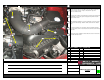
TORQUE RH SIDE SHOWN ITEM OPERATION LH SIDE SHOWN 10 10 10 Remove the fourteen 12mm bolts holding the lid to the main supercharger housing. NOTICE: One 12mm bolt at the back of the supercharger is very difficult to get to with the cowl over-hang. A swivel socket and extension may be needed to acccess and remove. 3 BOLTS CIRCLED 20 Pull each fuel rail up off of the supercharger (pulling all eight fuel injectors out of the supercharger housing).
TORQUE ITEM 10 10 OPERATION 20 NOTICE: No smoking, flames, or sparks around the fuel system. The fuel line and fuel rail can give off fumes that are flammable and may ignite if there is any form of spark or open flame near it. 10 Remove four of the fuel injectors from one fuel rail with a flat blade screwdriver. Set the tip of the screwdriver between the flange in the fuel rail (where the fuel injector connects), and one of the ears of the injector retaining clip.
TORQUE ITEM OPERATION 10 10 Assemble the intercooler stop by placing the rubber foot (A) over the end of the aluminum spacer (B) that is drilled and tapped for an M4 thread. 20 Apply Vibra Stop to the threads of the M4x16mm socket head cap screw (C). Tighten the M4 screw until the rubber stop begins to deform. 30 Apply Vibra Stop to the tapered face of the M6x16mm countersunk bolt (D), insert into shaker supercharger lid (E). Do not wait for the Vibra Stop to dry before inserting.
TORQUE ITEM OPERATION 10 Using a clean cloth rag and brake cleaner, clean the interior of the intake snorkel, and the machined mating faces at either end. Let air dry or blow out with compressed air if available. 20 Apply silicone O-ring lubricant to the large O-ring (A). 30 40 Install the large O-ring over the slotted end of the supercharger intake snorkel (B). The O-ring will sit in the groove milled in the perimeter of the snorkel.
TORQUE ITEM OPERATION NOTICE: The TMAP sensor and harness will be pointed in the reverse direction then what was instructed on Page 9 (pointing towards the driver side instead of the passenger side). Disregard sensor orientation in the following pages. It can be installed facing the driver side, but Saleen recommends the sensor face the passenger side for ease of connector accessibility. 20 10 Retrieve the supercharger lid gasket (A) and set it onto the supercharger housing.
TORQUE ITEM OPERATION 1 OF 8 SHOWN 30 10 NOTICE: No smoking, flames, or sparks around the fuel system. The fuel line and fuel rail can give off fumes that are flammable and may ignite if there is any form of spark or open flame near it. 20 10 Set the fuel rail assembly onto the supercharger. Press each fuel rail downward and make sure each fuel injector is seated into the supercharger housing. 20 Connect the fuel rail electrical connector to the fuel rail module located on the driver (LH) side.
TORQUE 10 ITEM OPERATION RH SIDE SHOWN - LH TYPICAL 10 Re-assemble the strut tower bracket to the strut tower bar. The allen head bolt with washer will face forward with a washer, lock washer, and nut facing towards the blukhead. 20 Place each strut tower bracket back onto the strut tower (over the strut studs). Re-install and tighten the four 13mm nuts (two per strut tower) and torque to 26 Lb-ft +/- 3.9 Lb-ft.
TORQUE ITEM OPERATION 10 10 20 Disconnect the engine harness ACT connector from the ACT sensor. To disconnect, depress the tab on the top of the connector and pull to remove. 20 Using a 19mm wrench, remove the ACT sensor from the supercharger housing (located on the driver side near the front of the supercharger). 30 Apply PTFE Instant Pipe Sealant to the threads of the supplied Allen plug (A). NOTICE: Saleen recommends the use of Vibra-Tite 46025 PTFE Pipe Sealant.
TORQUE ITEM OPERATION 10 Remove the electrical tape where the ACT sensor harness meets the engine harness. 20 Peel back the wiring convolute and cut the gray and gray with red stripe wires on the engine harness side of the butt connectors. 20 ITEM PART NUMBER QTY.
TORQUE ITEM OPERATION NOTICE: These steps are only required if you will be connecting the Saleen boost and air charge temp gauge kit. 10 Using wire cutters, cut the gray wire with single pin connector off at the ACT sensor connector. Strip approximately 1/4in of insulation from the end of the gray wire. The wire will be inserted into the butt connector that will be used to connect the gray wires coming from the engine and TMAP harnesses on the next page.
TORQUE ITEM OPERATION 10 Retrieve the TMAP sensor wiring harness (A), plug the 5-pin connector into the TMAP sensor, and route the harness around the front of the supercharger housing. 20 Untape the wiring convolute where the gray, gray with red stripe, and brown wires come out of the convolute. Tuck the brown wire back into the convolute, and retape the convolute. 30 Cut 3.
TORQUE ITEM OPERATION 10 Lightly place the supercharger lid snorkel onto the supercharger lid. Lightly tap the back of the lid (portion near the bulkhead) downward till the snorkel seats to the lid. 20 Obtain the four Allen head bolts (A) (with a collar above the threads). Apply Vibra Seal to the threads. Install three bolts on the passenger side rear corner of the lid snorkel and one bolt on the driver side rear corner. Torque each bolt to 18 Lb-ft +/- 2.7 Lb-ft.
TORQUE ITEM OPERATION 10 20 Insert the take-off Ford throttle body gasket (removed on Page 5), into the groove in the front of the inlet tube. Make sure the gasket is fully seated into the groove. NOTICE: If the motor is a relatively high mileage motor, a brand new replacment may need to be aquired from Ford. It is the standard throttle body gasket for a 4.6L 3V GT (2005 to 2010). 20 Using the four 10mm bolts, install the stock throttle body onto the inlet assembly.
TORQUE ITEM OPERATION 10 20 10 30 20 30 40 Plug in the throttle control electrical connector into the passenger (RH) side of the throttle body. Press the plug onto the throttle body connector until it is fully seated, and then slide the red locking tab towards the throttle body to lock the connector into place. Connect the throttle position connector to the driver (LH) side of the throttle body.
TORQUE ITEM OPERATION 30 10 Retrieve the air intake snorkel (with attached lid) and slide the throttle body portion onto the throttle body. Use a flat blade screwdriver to tighten the clamp. 20 Secure the air box lid to the air box. Slide the lid over the tabs in the air box and press to the lid down onto the air box. Make sure both clasps on the air box (facing the passenger compartment) are fully engaged. 30 Re-connect the MAF pigtail to the sensor. Press the MAF connector onto the sensor.
TORQUE ITEM OPERATION 10 20 10 Retrieve the air intake snorkel (with attached lid) and slide the throttle body portion onto the throttle body. Use a flat blade screwdriver to tighten the clamp. Secure the air box lid to the air box. Slide the lid over the tabs in the air box and press to the lid down onto the air box. Make sure both clasps on the air box (facing the driver side fender) are fully engaged.
TORQUE ITEM OPERATION NOTICE: No smoking, flames, or sparks around the battery. Batteries can give off fumes that are flammable and may ignite if there is any form of spark or open flame near it. 10 10 1 ITEM Connect the positive battery cable to the positive battery post ( The post nearest the passenger (RH) fender). Using an 8mm socket, tighten the clamp to 71 Lb-in +/- 10.6 Lb-in with a torque wrench. Re-cover the clamp with the red boot. PART NUMBER QTY. DESCRIPTION TORQUE NOTES: 1 71 +/- 10.
Post-Installation Review Please take the time to read the information provided. If you are installing this kit, and not the vehicle owner, please keep this page with the vehicle for the vehicle owner to review. Post-Installation Review: • Make sure that all electrical connections have been made • Check the vehicle for any coolant or fuel leaks • Verify that the intercooler water pump is running when the engine is running.