
Installation Guide

Americana Mailboxes – 2100 Series
Rear Loading Installation Instructions
Thank you for selecting Salsbury’s 2100 series Americana mailbox units. We are confident that the quality and construction of the mailboxes will
prove to be a good investment. The units are fully assembled and ready to be installed. All 2100 series units have the same outside dimensions
regardless of individual door size. They are designed to be stacked two (2) high and mount adjacent to each other or between wall studs. These
instructions are intended to assist you in a typical wall installation, and it should be understood that they can be modified depending upon your
choice in fasteners and materials. It is also recommended to have the units present before starting the wall construction to obtain the best possible
installation.
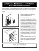
Typical Installation (Model 2130RL Shown) Notes
1. Wall opening and lumber frame must be square.
SALSBURY INDUSTRIES
1010 East 62
nd
Street, Los Angeles, CA 90001-1598
Phone: 1-800-624-5269 Int’l Phone: 323-846-6700
Fax: 1-800-624-5299 Int’l Fax: 323-846-6800
Installation instructions are provided as general guidelines. It is advised that a professional installer be consulted. Salsbury Industries assumes no product assembly or installation liability.
Copyright © 2006 Salsbury Industries. All rights reserved.
Standard Dimensions (Model 2114RL Shown)
2. Mailboxes should be shielded from direct weather conditions.
3. Store keys in a safe place until ready for use.
4. Hardware is not included to fasten unit into rough opening.
Americana Mailbox Instructions
1. The mailboxes are to be recessed in a typical wall that is framed
with 2” x 4” wall studs. Allowing approximately 24” for the width of
each mailbox column and any amount of desired space on each side
of the installation, frame out the perimeter of the wall and secure to
the floor. A platform 10”H x 16”D should be constructed for the base
of the installation and joined with the wall frame. Allowing at least a
53”H opening from the platform, position studs 24” on center leaving
a 22-1/2”W opening for each column of mailboxes to be installed.
(Note, when space is limited, you can eliminate the studs and attach
the modules to each other.) Add additional studs where needed for
drywall support. Finish the wall and center studs with drywall so all
front view surfaces are on the same plane.
2. The units will be secured to the studs positioned 24” on center.
On the front of the unit, drill four evenly spaced holes through the
flange on each side of the unit. Place the first unit on the platform
and secure it to the studs using 2” wood screws. Place the second
unit on top of the first and secure the same way. If securing the rear
loading modules to each other (without studs), overlap the flanges
and secure with sheet metal screws.
3. If necessary, fasten the lower unit to the platform by drilling two
holes through the bottom of the back of the unit and secure with 2”
wood screws. Likewise, fasten the top module to the bottom module
using sheet metal screws. This is recommended if not securing to
wall studs.
4. The installation of the trim at the front of the modules, which is
optional, is the last step in the installation process. There is enough
trim in each kit for three (3) mailbox columns. Fasten the clips to the
wall using 1” wood screws around the perimeter of the boxes and
between the columns. The trim should overlap the seam of the
module and drywall. After measuring the length of the seam to be
covered, cut the trim to size, mitering the corners at a 45º angle and
clip on.