
Instructions / Assembly


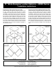


Table Of Contents

SALSBURY INDUSTRIES
18300 Central Avenue, Carson, CA 90746-4008
Phone: 1-800-562-5377 Int’l Phone: 323-846-6700
Fax: 1-800-562-5399 Int’l Fax: 323-846-6800
www.lockers.com engineering
@lockers.com
Installation instructions are provided as general guidelines. It is advised that a professional installer be consulted. Salsbury Industries assumes no product assembly or installation liability.
Copyright © 2020 Salsbury Industries. All rights reserved. (Revision 07, 2/2//2017) Page 1 of 7
15" Wide Designer Lockers – 20000 Series
Installation Instructions
Thank you for selecting Salsbury 20000 Series 15" Wide Designer Lockers. We are confident that the quality and construction of the lockers will
prove to be a good investment. These instructions are intended to assist you in a typical wall-anchored or back-to-back locker installation.
Individual job conditions will dictate the type of fasteners and whether the lockers must be anchored to the wall, the floor, or both.
The Salsbury 20000 Series 15" Wide Designer Lockers require
minimal assembly. The basic lockers are factory assembled. It may
be necessary to install the bases onto the floor, the lockers onto the
bases and to each other, the optional side panels to the exposed sides
of the lockers, and the lockers to a wall. See reverse side for
illustration of three lockers being installed.
Hardware Supplied with Each Locker
1. (1) Metal wall strap with three holes to attach locker to wall or back-to-
back. Bend the strap to tie locker to wall as shown in illustration.
2. (4) #8 x 5/8” long pan head sheet metal screws to attach strap to top
of lockers back-to-back or between locker and wall.
3. (2) 10-24 x 1-1/4” long pan head machine screws to fasten lockers
together side-by-side. Mating t-nuts are pre-installed in locker walls.
See reverse side for illustration of three lockers being installed.
4. (2) 1-1/4” long wood screws to attach side panel to locker.
5. (1) Number plate.
Installation Instructions
1. Wooden slats are attached to the bottom of the base with finishing
nails to support the unit during shipping - remove them by tapping them
away from the base with a mallet, then remove any remaining finishing
nails.
Bases s
hould be set in place and leveled. The rear edge of the base
should touch the wall or the other base if lockers are installed back-to-
back. There are 1-wide and 3-wide bases.
2. If the back of the locker is against a wall, bend the metal strap as
shown in the illustration. Set the locker on the base spaced 5/8” from the
wall for ventilation air. The metal straps will be installed in Step 5 below.
Leave the metal strap flat for fastening lockers back-to-back. Allow a 1-
1/4” ventilation space between the backs of lockers if lockers are back-to-
back and side panels are being installed. The metal straps will be
installed in Step 5 below.
Lockers alongside a wall with padlock type locking must be spaced 5/8”
from the side wall to allow swing room for the padlock.
3. Bolt multiple lockers together through the two unused holes and tee
nuts near the door hinges.
4. Attach the finished side panels flush with the front of the locker body
(not the door) allowing the excess to cover the 5/8” rear air space.
5. Once the lockers are plumb and level, attach the bent or flat
metal straps to the top of the lockers and to the wall or other
lockers as required.
6. Peel backing from number plate, align, and press into recess.
Illustration – 1 Locker