
Installation Sheet
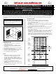
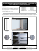

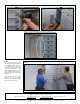

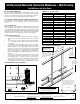

Figure 1
4C Recessed Mounted Horizontal Mailboxes – Connector Kit
Front Loading Unit Installation Instructions
Rough Opening
Height: See chart on page 6.
Width: To establish the size of the rough opening(s) in the wall(s) you
will be installing your mailbox configuration(s) into, calculate the overall
width of the total amount of units per wall installation; then subtract 3/4”
from the width grand total.
Example: (2) double-column mailboxes are to be installed.
• Each unit is 31-1/8” wide x 2 units = 62-1/4”
• 62-1/4” - 3/4” = 61-1/2” required for rough opening.
STEP 1
Place the first unit into the rough opening (see figure 1). Open the master door(s) to locate the 2x4 mounting holes on the inside corner of the mailbox’s trim
panel (see figure 2 for the difference between the 2x4 mounting holes and the connector kit mounting holes). Attach unit to the 2x4 wood framing (using the
provided #8 square drive x 2” long wood screws) on the side, top and bottom sections of the mailbox unit (see figures 3 through 6 on the next page).
Figure 2
Connector kit
mounting hole
2 x 4
mounting hole
Connector bar
corresponds to
unit height
Page 2 of 6
Hardware required for installation
-Connector #8 x 1/2” pan head self
tapping machine screws (provided
with each 4C Connector Kit)
-#8 square drive x 2” long
wood screws
(provided with mailbox)
Installation instructions are provided as general guidelines. It is advised that a professional installer be consulted. Salsbury Industries assumes
no product assembly or installation liability. Copyright © 2015 Salsbury Industries. All rights reserved. (Rev. 20, 02/10/2017)
SALSBURY INDUSTRIES
1010 East 62nd Street, Los Angeles, CA 90001-1598
Phone: 800-624-5269 Int’l Phone: 323-846-6700 Fax: 800-624-5299 Int’l Fax: 323-846-6800
www.mailboxes.com engineering@mailboxes.com