
Installation Sheet
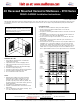
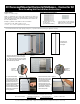
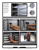
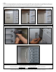
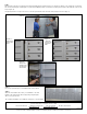
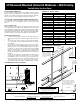

Figure 7 Figure 8 Figure 9
STEP 2
Locate the connector kit mounting holes on the opposite connecting side of the mailbox unit (see Step 1-Figure 2 for hole identification). Align the holes
on the 4C connector bar with the holes located on the mailbox unit (see figures 7-9). Attach connector bar to the mailbox unit with the provided #8 x
1/2” pan head self tapping machine screws (see figures 10-11). The installation should now look like figure 12 - below.
Page 4 of 6
Side View
Unit shown
with master
door open
Figure 10 – Top side of unit facing 4C Connector Bar Figure 11 – Bottom side of unit facing 4C Connector Bar
Figure 12 – 4C Connector Bar is now attached to mailbox unit
Installation instructions are provided as general guidelines. It is advised that a professional installer be consulted. Salsbury Industries assumes
no product assembly or installation liability. Copyright © 2015 Salsbury Industries. All rights reserved. (Rev. 20, 02/10/2017)
SALSBURY INDUSTRIES
1010 East 62nd Street, Los Angeles, CA 90001-1598
Phone: 800-624-5269 Int’l Phone: 323-846-6700 Fax: 800-624-5299 Int’l Fax: 323-846-6800
www.mailboxes.com engineering@mailboxes.com