
Installation Sheet
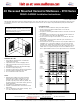
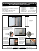
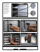
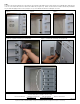
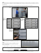
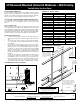

Figure 13
STEP 3
With assistance, align the second unit up to the first unit, butting the trim of both units up to one another (see figures 13-15). Attach the second unit to
the connector bar (using the remaining #8 x 1/2” pan head self tapping machine screws) via the mounting holes located on the inside trim of the second
unit (see figure 16).
Using #8 square drive x 2” long wood screws, secure the top and bottom of the unit to the wall (see figures 5 and 6 on page 3).
Page 5 of 6
Figure 14 –
Align units up
next to each
other.
Figure 16–
Secure units
together using
connector ma-
chine screws
Figure 15
– Butt each
unit’s trim up
against the
other.
STEP 4
If necessary, repeat this process for additional units to be installed.
STEP 5
Attach the last mailbox unit used in your installation to the wall
framing on the opposite side of the rough opening using #8 square
drive x 2” long wood screws.
This completes installation of your mailboxes using the 4C Connector Kit(s).
Installation instructions are provided as general guidelines. It is advised that a professional installer be consulted. Salsbury Industries assumes
no product assembly or installation liability. Copyright © 2015 Salsbury Industries. All rights reserved. (Rev. 20, 02/10/2017)
SALSBURY INDUSTRIES
1010 East 62nd Street, Los Angeles, CA 90001-1598
Phone: 800-624-5269 Int’l Phone: 323-846-6700 Fax: 800-624-5299 Int’l Fax: 323-846-6800
www.mailboxes.com engineering@mailboxes.com