
Installation Sheet


SALSBURY INDUSTRIES
1010 East 62
nd
Street, Los Angeles, CA 90001-1598
Ph: 1-800-624-5269 Int’l Ph: 323-846-6700
Fx: 1-800-624-5299 Int’l Fx: 323-846-6800
www.mailboxes.com engineering@mailboxes.com
Installation instructions are provided as general guidelines. It is advised that a professional installer be consulted. Salsbury Industries assumes no product assembly or installation
liability. Copyright © 2017 Salsbury Industries. All rights reserved. (02/10/17) Page 2 of 3
3800 Series Surface Mount Enclosures
For 3700 Series 4C Front Loading Recessed Mounted Horizontal Mailboxes
Installation Instructions
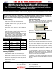
Installing the Wall Fasteners
Install Type A wood screws, Fig. 3 (or anchors and fasteners) into
all of the outermost slots (or slots engaging wood studs) in the rear
panel. Install two (2) of the Type A wood screws, not provided, (or
anchors and fasteners, not provided) in the rear flange of the top
panel and in the rear flange of the bottom panel so that the four (4)
screws go through the elongated slots in the rear flanges and into
the wood studs. See the “Screw Locations”, Fig. 4.
Screw Locations
Fig. 4 identifies the locations of the Type A fasteners that are used
to attach the enclosure to the wall studs.
Installing the Mailbox Unit
Lifting and installing the mailbox unit into the enclosure is a two (2)
person operation. Open appropriate compartment doors to provide
handholds. Lift the mailbox unit and carefully slide it into the
enclosure until the front peripheral flange is flush against the front
flanges of the enclosure. See Fig. 5.
Fastening the Mailbox Unit to the Enclosure
Open the master door(s) of the mailbox unit until the hold-open rods
at the top inside corners of the doors engage. Install Type B self-
tapping machine screws (provided) in the flanges all around the four
(4) sides of the mailbox unit just behind the master door(s). See the
following illustrations to locate the flanges. Pilot holes are provided
for the screws in the flanges. The double column mailbox unit
shown uses four (4) screws each along the top and bottom flanges.
The single column mailbox unit (not shown) uses only two (2)
screws each along the top and bottom. See Fig. 6.
Type A
Type A
TOP
BOTTOM
Fig. 3
Fig. 4
Fig. 5
Type A
Type B
Type B
Type B
TOP
BOTTOM
Fig. 6