
Instructions / Assembly

SALSBURY INDUSTRIES
1010 East 62
nd
Street, Los Angeles, CA 90001-1598
Phone: 1-800-562-5377 Int’l Phone: 323-846-6700
Fax: 1-800-562-5399 Int’l Fax: 323-846-6800
Installation instructions are provided as general guidelines. It is advised that a professional installer be consulted. Salsbury Industries assumes no product assembly or installation liability.
Copyright © 2008 Salsbury Industries. All rights reserved. (Rev.03, 7/17/2008)
Vented Lockers – 76000 Series
Box Style Installation Instructions
Thank you for selecting Salsbury’s vented box lockers. We are confident that the quality and construction of the lockers will prove to be a good
investment. These instructions are intended to assist you in assembling the lockers. The lockers should then be placed in the installed location and
anchored to the floor, wall, or to both. Individual job conditions will dictate the type of anchor fasteners.
Preliminary Note
Please read the complete assembly instructions before attempting to
assemble the lockers. Check the materials to be sure that they are
correct for the job and that there is no damage.
Be careful to use the correct hardware. Use screw no. 1 all around
with screw heads out, except where noted. Lockers should be
assembled in groups as indicated in the order of the drawings.
The essential tools required for assembling the lockers are a Phillips
screwdriver, a 3/8” nut driver, and 2 small nail punches or drift pins
for hole alignment. The lockers should be assembled on a flat level
surface and installed in position, anchoring to the floor or wall, as
required.
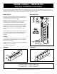
See the illustration to the right to identify the locker parts. Note that
the sloping hood, front base, end base, and name plate are optional
items and their assembly is covered by a separate installation
instruction.
Assembly
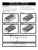
1. Fasten a top, bottom, and side to a back. The top and bottom are
identical parts and should have the flanges down. Insert a rear leg
and fasten. See Illustration 1.
2. Fasten the shelves in place with the flanges down and the tapered
end flanges in front. See Illustration 2.
For a single locker, skip to Step 4.
Illustration 1
Parts Identification
Illustration 2