
Instructions / Assembly

Vented Lockers – 76000 Series
Box Style Installation Instructions
Assembly (continued)
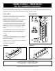
3. Position additional sides, backs, tops, bottoms, and shelves and
fasten in place. See Illustration 3.
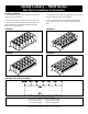
4. Add a last side (flange in) and the other leg. See Illustration 4.
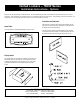
5. Attach the door and frame assemblies, ensuring that the front
edges of the sides are inside a frame assembly flange and not
between frames. See Illustration 5.
Illustration 3
Illustration 4
6. Fasten the last door and frame assembly into place, ensuring that
they are all faste
ned correctly. See Illustration 6.
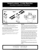
7. Finally, install frame hasps into frame and lock hole fillers into
doors. If there are built-in locks, install locks instead of lock hole
fillers.
Illustration 5
Illustration 6
Side Panel Hole Locations for Shelves
SALSBURY INDUSTRIES
1010 East 62
nd
Street, Los Angeles, CA 90001-1598
Phone: 1-800-562-5377 Int’l Phone: 323-846-6700
Fax: 1-800-562-5399 Int’l Fax: 323-846-6800
Installation instructions are provided as general guidelines. It is advised that a professional installer be consulted. Salsbury Industries assumes no product assembly or installation liability.
Copyright © 2008 Salsbury Industries. All rights reserved. (Rev.03, 7/17/2008)