9049 Tyler Blvd. • Mentor, Ohio 44060 Phone (440) 974-8888 • Fax (440) 974-0165 Toll-Free Fax 800-841-8003 • buyersproducts.
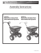
by Buyers Check contents of box against the parts list to make sure all components are included. When ordering replacement or spare parts refer to the parts list for part numbers.
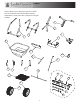
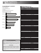
by Buyers TOOLS NEEDED FOR ASSEMBLY Bill of Materials (for all figures) WB100A = CS / WB200A = SST • (2) 10mm Wrenches • (2) ½" Wrenches • (1) Slotted Screwdriver • (1) Pliers • (1) 3mm Allen Wrench (included) ITEM 1 2 3 4 5 6 7 8 9 10 11 12 13 14 15 16 17 18 19 20 21 22 23 24 Fastener Selection Guide M6x50 (4) M6x70 (2) M6x60 (4) M6x45 (3) M6x40 (5)
by Buyers 3 M6x60 2 17 M6x60 FRONT 1. Loosely assemble the Lower Frame(2) to the Hopper Support Assembly(3) including the two Hopper Support Brackets(17). Start the nuts, but do not fully tighten.
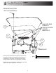
by Buyers 17 M6x45 WITH M6 FLAT WASHERS (x2) 12 5 13 15 21 23 M6x40 M6x45 23 22 20 24 14 21 DRIVE GEAR MOUNTING HOLE 2. Loosely assemble the axle components to the frame A. Attach the Drive Gear(15) to the axle with a m6x40 bolt B. Position the Spinner Shaft Support(20) and orient it as shown C. Add one Shim Washer(21) as shown D. Add the two stainless steel Locking Collars(24) E. Add two plastic axle Bushings(22) F.
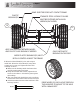
by Buyers MAKE SURE TIRE DOES NOT CONTACT FRAME PLASTIC BUSHING(22) STAINLESS STEEL LOCKING COLLARS MUST BE FASTENED WITH ALLEN WRENCH (INCLUDED) 13 12 ADD SHIM WASHERS BETWEEN WHEEL AND PLASTIC AXLE BUSHING IF NEEDED ONLY ONE PLASTIC BUSHING ON THIS SIDE INSIDE PLASTIC BUSHINGS(22) MUST BE FULLY SEATED AGAINST THE FRAME 5. Mount the Drive Wheel(12) to the axle using an m6x45 bolt. Mount the Coast Wheel(13) using shim washers and a cotter pin. Tighten the entire axle assembly as shown A.
by Buyers SET COAST WHEEL SPACING SO THAT THERE IS A MINIMAL GAP BETWEEN THE SHIM WASHER(21) AND THE COTTER PIN(23) 5. Continued The coast wheel's tire should not contact or rub any part of the frame. If it does, add shim washers to space it away. Make sure there is at least one shim washer between the hub and the cotter pin.
by Buyers M6x50 MACHINE SCREW WITH FLAT WASHER (4x) MAKE SURE REAR SCREWS GO THROUGH HOPPER SUPPORT BRACKETS(17) 4 17 17 6 SPINNER SHAFT 6. Position the spinner shaft straight and then loosely assemble the Hopper Assembly(4) and the Deflector Assembly(6) to the frame. The spinner shaft will go through a hole in the bottom of the hopper assembly. M6x50 7. Verify that the spinner shaft is still straight and fully tighten the hopper assembly to the frame.
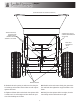
by Buyers (FRONT DEFLECTOR NOT SHOWN FOR CLARITY) TIGHTEN THESE BOLTS AFTER VERIFYING SPINNER SHAFT IS STRAIGHT AND AXLE SPACING IS STILL INTACT SPINNER SHAFT MUST BE STRAIGHT (PERPENDICULAR TO THE AXLE) GEARS MUST INTERFACE OR "MESH" RECHECK SPACING 8. Recheck the axle spacing to make sure that the plastic bushings and stainless steel collars are still in place against the frame. 10. Check that the axle rotates freely, the gears interface well and then tighten the support bracket to the frame. 9.
by Buyers DEFLECTOR NUTS MAY NEED TIGHTENED DEFLECTOR'S WINGNUTS SHOULD BE OUTSIDE OF FLAPS (AWAY FROM SPINNER) 12. The front deflector nuts may need tightened in order to keep the deflector straight. Also, be sure to mount the deflector so that the wingnuts are outside of the flaps (away from the spinner).
by Buyers 16 1 M6x40 LOWER LINKAGE MOUNTS TO THIS HOLE IN THE LINKAGE PLATE ASSEMBLY(16) 10 FIRST JAM NUT 10 HOPPER AND DEFLECTORS NOT SHOWN FOR CLARITY SECOND JAM NUT (MUST BE REMOVED TO MOUNT UPPER CONTROL ROD) 16 BEND IN LOWER LINKAGE IS NEAR THE END BY RESTRICTOR PLATE 11 M6x40 11 FIRST JAM NUT USED TO SET THE RESTRICTOR CONTROLS SECOND JAM NUT USED TO LOCK CONTROL ROD SETTING WHEN TIGHTENED WITH ½" WRENCHES RESTRICTOR PLATE (PRE-MOUNTED UNDER HOPPER) 7 9 1 10 M6x40 FIRST JAM NUT 13.
by Buyers 9 NOTE: THE HANDLE HEIGHT IS ADJUSTABLE. ANY TWO HOLES NEXT TO EACH OTHER MAY BE USED AS LONG AS BOTH BOLTS GO THROUGH THE HOLES IN THE UPPER FRAME ALSO. 7 STOP BOLT 10 M6x70 UPPER CONTROL ROD MAY BE MOUNTED ON INSIDE OR OUTSIDE OF CONTROL HANDLE 16. Using two m6x70 bolts, attach the Handle(9) and Control Handle Assembly(7) to the frame. 17. Attach the Upper Linkage(10) to the control handle assembly and the linkage plate assembly.
by Buyers SET CONTROL HANDLE TO "30" ADJUST RESTRICTOR SO IT IS FULLY OPEN (HOPPER NOT SHOWN FOR CLARITY) First jam nut must be adjusted so it is flush against the bracket when the restrictor plate is fully open and the control handle is at "30". Second jam nut must be removed before mounting upper linkage to linkage plate assembly. After controls are set, it must be re-mounted flush against bracket and tightened with 1/2" wrenches. 18.
by Buyers 8 M6x20 BOLTS 19. Using two M6x20 bolts, attach the Rear Deflector Assembly(8) to the Hopper Support Brackets (as shown).
by Buyers 18 20. Double check that all hardware is tight and the drive system turns properly (it should feel a bit snug). 3. Check that the Restrictor Plate and Linkage move freely. Clear out any debris between the Restrictor Plate and the Hopper. 4. Check that there is no debris in the Gears and that they move freely. 5. Check torque of all fasteners on a monthly basis. 21. Place the screen(18) inside the hopper. Operation 1.
by Buyers 16 9049 Tyler Blvd. • Mentor, Ohio 44060 Phone (440) 974-8888 • Fax (440) 974-0165 Toll-Free Fax 800-841-8003 • buyersproducts.com 3009791 Rev.