
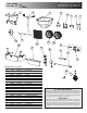
Replacement Part List


1
TM
9049 Tyler Blvd. • Mentor, Ohio 44060
Phone (440) 974-8888 • Fax (440) 974-0165
Toll-Free Fax 800-841-8003 • saltdogg.com
Assembly Instructions
WARNING
When filling hopper, make certain there are no large objects within the
material. Objects larger than the openings in the Screen may cause
the spreader to clog or even damage the drive system. Never leave
material in the hopper when not in use.
WB150BG Heavy-Duty Carbon Steel Walk
Behind Salt Spreader, Bulk Flow Gate
WB250BG Heavy-Duty Stainless Steel
Walk Behind Salt Spreader, Bulk Flow
Gate
Check contents of box against the parts list to make sure all
components are included. When ordering replacement or spare
parts refer to the parts list for part numbers.
TOOLS NEEDED FOR ASSEMBLY
• (2) 10mm Wrenches
• (2) 1/2 in Wrenches
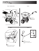
Attaching the Handle, Linkage Plate Assembly, and Lower
Linkage – Figures 2 – 6
A. Remove contents from box and place the preassembled por-
tion of the spreader upright on its wheels
B. Slide the Handle onto the spreader frame & line up the holes
C. Carefully insert the Lower Linkage into the Restrictor Plate
underneath the Hopper as shown. (The Lower Linkage has two
bent ends & the Upper Linkage has one threaded end)
D. Insert the other end of the Lower Linkage into the front hole
on the Linkage Plate Assembly
E. Attach the Linkage Plate Assembly and Handle to the Frame
using two M6x40 bolts as shown. Figure 6 shows the lower link-
age assembled (for reference).
NOTE: The Lower Linkage must be attached to the restric-
tor and the Linkage Plate Assembly before the Assembly is
attached to the frame. If the Linkage Plate Assembly is attached
to the Frame without the Lower Linkage, the Lower Linkage will
be very difficult to assemble and may cause the restrictor plate
to be broken during assembly
Attach Control Handle Assembly, Upper Linkage, & Rear
Deflector – Figure 7 & 8
F. Mount the Control Handle Assembly to the Handle using two
M6x40 bolts as shown.
G. Insert the Upper Linkage into the Control Handle as shown.
H. Thread one Jam Nut so that the Restrictor Plate underneath
the Hopper is fully closed when the Control Handle is at "30".
Assemble the second jam nut in this position to lock the linkage
in place.
I. Verify that the Restrictor Plate may be fully opened by pushing
the Control Handle forward.
J. Using two M6x20 bolts, attach the rear deflector.
Final Assembly
A. Check And Tighten All Fasteners – Make sure the Gearbox
turns freely when pushing and pulling the unit.
B. Place the Screen in the hopper.
C. Install the Rain Cover on the hopper.
Operation
1. Before filling Hopper, ensure that the Restrictor Plate is fully
closed and the screen is in place.
2. Move and tighten the stop bolt to the desired setting.
3. Begin moving forward with the spreader.
4. Pull the Control Handle back to the stop bolt to open
Restrictor Plate and allow material to flow.
5. Before stopping, push the Control Handle fully forward to
stop flow.
Maintenance
1. The Hopper and Spinner should be completely emptied and
cleaned before storage.
2. The Spreader should be washed and dried before storage.
3. Check that the Restrictor Plate and Linkage move freely. Clear
out any debris between the Restrictor Plate & the Hopper.
4. Check that there is no debris in the Gears & that they move
freely.
5. Check torque of all fasteners on a monthly basis.
Operation Notes:
1. The spreader is designed to be operated at a brisk walking
pace (approx. 3mph). Walking slower or faster will alter the distri-
bution pattern & amount of the material, as will the moisture con-
tent of the material & other environmental factors.
2. Grease may be applied to the Gearbox as desired.