
User Manual

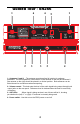
Table Of Contents
- p8
- User Manual
- Stage5_55_um
- Stage266 user manual
- Kilo_OM_5L_v2 - 副本
- Stage266 user manual
- Kilo_OM_5L_v2 - 副本
- Stage266 user manual
- pdftemp
- ENGLISH
- FRANÇAIS
- Introduction
- Tour d'horizon - Façade avant du SR55
- Tour d'horizon - Façade arrière du SR55
- Tour d'horizon - Façade avant du SR5
- Tour d'horizon - Façade arrière du SR5
- Tour d'horizon - SR5 / ST5
- Tour d'horizon - HT5
- Réglage et utilisation du système
- Stage 55 Series / Stage 5 Series
- Caractéristiques techniques
- DEUTSCHE
- ESPAÑOL
- Introducción
- Recorrido Guiado - Panel frontal del SR55
- Recorrido Guiado - Panel trasero del SR55
- Recorrido Guiado - Panel frontal del SR5
- Recorrido Guiado - Panel trasero del SR5a
- Recorrido Guiado - SR5 / ST5
- Recorrido Guiado - HT5
- Ajuste y utilización de su sistema
- Stage 55 Series / Stage 5 Series
- Especificaciones técnicas
- ITALIANO
- Introduzione
- Visita Guidata - il Pannello
- Frontale dell'SR55
- Visita Guidata - il Pannello Posteriore dell'SR55
- Visita Guidata - il Pannello
- Frontale dell'SR5
- Visita Guidata - il Pannello Posteriore dell'SR5
- Visita Guidata - l'ST5
- Visita Guidata - l'HT5
- Il Collegamento e l'Uso del
- Sistema Serie Stage 55 /Stage 5
- Specifiche
- Appendix A: Carrying Case
- Stage266 user manual
- pdftemp

Guided Tour - SR266
)2 dna 1( sannetnA :1 - The antenna mountings allow full rotation for optimum
placement. In normal operation, both Antenna 1 (the antenna on the left) and Antenna 2
(the antenna on the right) should be placed in a vertical position. Both antennas can be
folded inward for convenience when transporting.
2: Volume control - This knob sets the level of the audio signal being output through both
o
clockwisse.
utput jacks on the rear panel. Reference level is obtained when the knob is turned fully
3: ANT LEDs - When signal is being received, one of these will be lit , showing
you whether the (left) “1” or (right) “2” antenna is currently being used.
4: Power switch - Use this to turn the SR55 power on and off.
1
1
2
23
3
4
6
6
5
8