
User's Manual
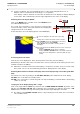
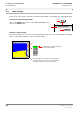
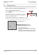
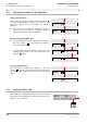

Table Of Contents
- General Safety Precautions
- List of Contents
- 1 Overview
- 2 Basic Settings; General Remarks about Operating
- 3 PPI Settings
- 3.1 Screen Stabilisation of the PPI: True Motion, Relative Motion
- 3.2 PPI Orientation: Head-Up, North-Up, Course-Up
- 3.3 Centering / Off-Centering of the Display (Center, Off-Center)
- 3.4 Range Selection (Range)
- 3.5 Range Rings, Grid
- 3.6 Own Ship Symbols and Target Symbols, Vectors, Past Position Plots
- 3.7 Trails
- 3.8 Setting the Display of Pre-planned Tracks
- 3.9 Defining the System Track and the Next Waypoint; System Track Display
- 3.10 Setting the Display of User Chart Objects on the RADARPILOT
- 3.11 Setting the Display of Charts and User Chart Objects on the CHARTRADAR
- 3.12 Setting the Display of the Map
- 3.13 Adjusting the Chart or Map to the Radar Video
- 4 Setting the Radar Function
- 4.1 Radar Function On/Off, Interswitch Functions, Master/Slave Switch-Over
- 4.2 Basic Setting of the Radar Video
- 4.3 Selection of the Antenna Revolution Rate
- 4.4 Radar Setting for High Speed of Own Vessel (HSC)
- 4.5 Radar Setting for the Display of RACON Codes
- 4.6 Radar Setting for SART Detection (X-Band only)
- 4.7 Suppression of the Synthetics and Video
- 5 Heading, Speed, Position
- 6 Bearing and Range
- 7 ARPA Functions
- 7.1 Symbols Used
- 7.2 Procedure of the Target Acquisition
- 7.3 Manual Target Acquisition
- 7.4 Automatic Target Acquisition; Settings of the Acquisition/Guard Zone
- 7.5 Deletion of Targets, Loss of Target
- 7.6 Target Data Display
- 7.7 Target Labels
- 7.8 Selecting the Reference Targets for Reference Target Tracking
- 8 EPA Functions (Electronic Plotting Aid)
- 9 Collision Avoidance (TCPA, CPA)
- 10 Trial Manoeuvres
- 11 Editing of Pre-planned Tracks
- 12 Editing the Map
- 13 Displays in the Multidisplay
- 14 Quick Info Box
- 15 Evaluation of the Radar Video
- 16 The Radar Keyboard
- 17 Alarm Management
- 18 List of Alarms
- 19 List of the Alarm Signal Outputs
- 20 Care and Maintenance Work
- 21 Performance Monitor
- 22 System Maintenance Manager
- 22.1 Determining the Versions of Software, Hardware and Documentation
- 22.2 Listing the System Faults
- 22.3 Off-Line Selfcheck
- 22.4 Checking / Correcting the Computer Time
- 22.5 Distribution and Deletion of Map Data; Data Saving
- 22.6 Exchanging Track Files between the Indicators; Data Saving
- 22.7 The Handling of Diskettes
- 22.8 Aborting and Restarting the Program of the Radar System

ED 3038 G 232 / 01 (2002-06)
Operating Instructions
13 Displays in the Multidisplay
13.2 Zoom Display
b_r1_e31.fm / 21.06.02
101
RADARPILOT / CHARTRADAR
☞ In this zoom display, the area enlargement factor is 9 (the linear enlargement factor is 3).
Only the video is contained in the zoom image, i.e. no synthetics.
If the display of trails is switched on for the PPI, the trails in the zoom display are always displayed
in true mode. This is indicated by a T in the upper right-hand corner of the zoom display.
Switching the Zoom Display On/Off
Click on the MENU button, and then click on the ZOOM button in
the USER SETTINGS menu.
As a result, the zoom frame is set in the PPI at a fixed position
around own ship’s position. The frame marks the area displayed in
enlarged form in the zoom display.
At the same time, the zoom display appears in the Multidisplay.
Positioning the Zoom Frame
Click into the zoom display; then, at the desired position in the PPI, press the DO key.
Alternatively: In the PPI, click on the zoom frame at its contour, position the zoom frame by means of the
trackball, and press the DO key.
☞ When the zoom frame reaches the PPI boundary, it is kept there so that it can be accessed at any
time. In this case too, the area marked by the frame is displayed in the zoom display.
Switching Over between a Fixed Zoom Display and a Zoom Display being Carried Along with Own
Ship
The switch-over is done by clicking on the FIX ABS / FIX REL button situated in the zoom display.
FIX ABS = the zoom frame has a fixed position.
FIX REL = the zoom frame is carried along with own ship, maintaining a constant distance and bearing
relative to own ship.
Carrying the Zoom Display Along with a Target
Click on the target with the MORE key, and then click on ZOOM FIXED ON TARGET (by means of the
DO key). The FIX ABS / FIX REL button situated in the zoom display now indicates by means of FIX
TGT that the zoom frame is being carried along with the radar target displayed in the frame.
☞ By clicking on the FIX ABS / FIX REL button or by positioning the zoom frame, the zoom frame is
set at a fixed position.
MENU
MENU
USER SETTINGS
1.DO
ZOOM
3.DO
2.DO
Clicking causes a switch-over between a fixed zoom frame
(display FIX ABS) and a zoom display which is carried along
(with own ship’s position) (display FIX REL).
Display FIX TGT: The zoom frame is carried along with a
radar target.
T = trails are displayed as true trails in the zoom display
ZOOM OFF
FIX ABS
T
FIX REL
This menu appears after the MORE key has been used to click into the
zoom display.
- Clicking on ZOOM OFF switches off the zoom display.
- Clicking on FIX REL or FIX ABS switches over between a fixed zoom
display and a zoom display which is carried along (with own ship’s
position).