
User's Manual
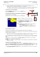
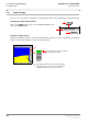
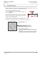
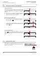

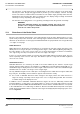
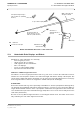
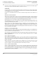
Table Of Contents
- General Safety Precautions
- List of Contents
- 1 Overview
- 2 Basic Settings; General Remarks about Operating
- 3 PPI Settings
- 3.1 Screen Stabilisation of the PPI: True Motion, Relative Motion
- 3.2 PPI Orientation: Head-Up, North-Up, Course-Up
- 3.3 Centering / Off-Centering of the Display (Center, Off-Center)
- 3.4 Range Selection (Range)
- 3.5 Range Rings, Grid
- 3.6 Own Ship Symbols and Target Symbols, Vectors, Past Position Plots
- 3.7 Trails
- 3.8 Setting the Display of Pre-planned Tracks
- 3.9 Defining the System Track and the Next Waypoint; System Track Display
- 3.10 Setting the Display of User Chart Objects on the RADARPILOT
- 3.11 Setting the Display of Charts and User Chart Objects on the CHARTRADAR
- 3.12 Setting the Display of the Map
- 3.13 Adjusting the Chart or Map to the Radar Video
- 4 Setting the Radar Function
- 4.1 Radar Function On/Off, Interswitch Functions, Master/Slave Switch-Over
- 4.2 Basic Setting of the Radar Video
- 4.3 Selection of the Antenna Revolution Rate
- 4.4 Radar Setting for High Speed of Own Vessel (HSC)
- 4.5 Radar Setting for the Display of RACON Codes
- 4.6 Radar Setting for SART Detection (X-Band only)
- 4.7 Suppression of the Synthetics and Video
- 5 Heading, Speed, Position
- 6 Bearing and Range
- 7 ARPA Functions
- 7.1 Symbols Used
- 7.2 Procedure of the Target Acquisition
- 7.3 Manual Target Acquisition
- 7.4 Automatic Target Acquisition; Settings of the Acquisition/Guard Zone
- 7.5 Deletion of Targets, Loss of Target
- 7.6 Target Data Display
- 7.7 Target Labels
- 7.8 Selecting the Reference Targets for Reference Target Tracking
- 8 EPA Functions (Electronic Plotting Aid)
- 9 Collision Avoidance (TCPA, CPA)
- 10 Trial Manoeuvres
- 11 Editing of Pre-planned Tracks
- 12 Editing the Map
- 13 Displays in the Multidisplay
- 14 Quick Info Box
- 15 Evaluation of the Radar Video
- 16 The Radar Keyboard
- 17 Alarm Management
- 18 List of Alarms
- 19 List of the Alarm Signal Outputs
- 20 Care and Maintenance Work
- 21 Performance Monitor
- 22 System Maintenance Manager
- 22.1 Determining the Versions of Software, Hardware and Documentation
- 22.2 Listing the System Faults
- 22.3 Off-Line Selfcheck
- 22.4 Checking / Correcting the Computer Time
- 22.5 Distribution and Deletion of Map Data; Data Saving
- 22.6 Exchanging Track Files between the Indicators; Data Saving
- 22.7 The Handling of Diskettes
- 22.8 Aborting and Restarting the Program of the Radar System

ED 3038 G 232 / 01 (2002-06)
Operating Instructions
13 Displays in the Multidisplay
13.4 Wind/Set+Drift Display
b_r1_e31.fm / 21.06.02
103
RADARPILOT / CHARTRADAR
13.4 Wind/Set+Drift Display
If there is a wind sensor connected, the wind data and the set and drift caused by the current can be
displayed numerically and graphically on the Wind/Set+Drift Display.
Switching the Wind/Set+Drift Display On/Off
Click on the MENU button. Then, in the USER SETTINGS menu,
click on the WIND button.
Specifying whether the Wind is to be Displayed True or Relative
Switch-over is performed by clicking into the top right-hand area
(T or R) of the Wind/Set+Drift Display.
Specifying whether the Wind Speed is to be Displayed in kt or in m/s
The switch-over is performed by clicking into the numerical field of the wind speed.
MENU
MENU
USER SETTINGS
1.DO
WIND
3.DO
2.DO
R = relative wind, T = true wind;
switch-over by clicking
Direction and speed of the current,
The values are determined from the available sensor data. If not all of the
necessary data are available, the data displayed do not correctly represent
the drift vector.
Example: If only the longitudinal speed through the water (from an EM log)
and the speed vector over ground (from GPS) are available, the displayed
set and drift values indicate the offset caused by the current and wind.
Ship symbol represents the present Gyro Heading
Yellow arrow pointing inwards: Wind direction
Blue arrow pointing outwards: Direction of the current
Red line: Actual course = Gyro Heading + drift angle
Wind direction and wind speed