
User's Manual

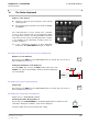
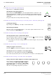


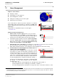


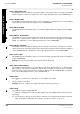
Table Of Contents
- General Safety Precautions
- List of Contents
- 1 Overview
- 2 Basic Settings; General Remarks about Operating
- 3 PPI Settings
- 3.1 Screen Stabilisation of the PPI: True Motion, Relative Motion
- 3.2 PPI Orientation: Head-Up, North-Up, Course-Up
- 3.3 Centering / Off-Centering of the Display (Center, Off-Center)
- 3.4 Range Selection (Range)
- 3.5 Range Rings, Grid
- 3.6 Own Ship Symbols and Target Symbols, Vectors, Past Position Plots
- 3.7 Trails
- 3.8 Setting the Display of Pre-planned Tracks
- 3.9 Defining the System Track and the Next Waypoint; System Track Display
- 3.10 Setting the Display of User Chart Objects on the RADARPILOT
- 3.11 Setting the Display of Charts and User Chart Objects on the CHARTRADAR
- 3.12 Setting the Display of the Map
- 3.13 Adjusting the Chart or Map to the Radar Video
- 4 Setting the Radar Function
- 4.1 Radar Function On/Off, Interswitch Functions, Master/Slave Switch-Over
- 4.2 Basic Setting of the Radar Video
- 4.3 Selection of the Antenna Revolution Rate
- 4.4 Radar Setting for High Speed of Own Vessel (HSC)
- 4.5 Radar Setting for the Display of RACON Codes
- 4.6 Radar Setting for SART Detection (X-Band only)
- 4.7 Suppression of the Synthetics and Video
- 5 Heading, Speed, Position
- 6 Bearing and Range
- 7 ARPA Functions
- 7.1 Symbols Used
- 7.2 Procedure of the Target Acquisition
- 7.3 Manual Target Acquisition
- 7.4 Automatic Target Acquisition; Settings of the Acquisition/Guard Zone
- 7.5 Deletion of Targets, Loss of Target
- 7.6 Target Data Display
- 7.7 Target Labels
- 7.8 Selecting the Reference Targets for Reference Target Tracking
- 8 EPA Functions (Electronic Plotting Aid)
- 9 Collision Avoidance (TCPA, CPA)
- 10 Trial Manoeuvres
- 11 Editing of Pre-planned Tracks
- 12 Editing the Map
- 13 Displays in the Multidisplay
- 14 Quick Info Box
- 15 Evaluation of the Radar Video
- 16 The Radar Keyboard
- 17 Alarm Management
- 18 List of Alarms
- 19 List of the Alarm Signal Outputs
- 20 Care and Maintenance Work
- 21 Performance Monitor
- 22 System Maintenance Manager
- 22.1 Determining the Versions of Software, Hardware and Documentation
- 22.2 Listing the System Faults
- 22.3 Off-Line Selfcheck
- 22.4 Checking / Correcting the Computer Time
- 22.5 Distribution and Deletion of Map Data; Data Saving
- 22.6 Exchanging Track Files between the Indicators; Data Saving
- 22.7 The Handling of Diskettes
- 22.8 Aborting and Restarting the Program of the Radar System

ED 3038 G 232 / 01 (2002-06)
Operating Instructions
16 The Radar Keyboard
b_r1se16.fm / 21.06.02
115
RADARPILOT / CHARTRADAR
For Section 4.7,
Suppression of the Synthetics and Video
(see page 53):
Suppression of the Synthetics or Video
If the SYNTH OFF key is pressed, no synthetics are displayed on the PPI.
For as long as the key VIDEO OFF is pressed, no video is displayed.
For Section 6.2,
Variable Range Markers (VRM’s)
(see page 63):
Using One VRM
If the VRM is in the switched-off state, it is switched on by pressing of the key VRM1
or VRM2, and the rotary knob VRM is assigned to that VRM. The desired distance can
now be set by means of the rotary knob. If the VRM key that was pressed previously is
pressed again, this switches the VRM off.
Switching the Second VRM On and Using It
If one VRM is in the switched-on state, the second VRM too is switched on by pressing of the other VRM
key, and the rotary knob VRM is assigned to the second VRM. The desired distance of the second VRM
can now be set by means of the rotary knob.
Using Both VRM’s
If both VRM’s are switched on, the first pressing of a VRM key assigns the rotary knob to that VRM, and
the second pressing in succession causes switch-off of the VRM.
☞ The arrow in front of the VRM area indicates the VRM which can currently be altered by means of
the rotary knob.
☞ If the display range was reduced when the VRM was in the switched-on state, it may be that the
VRM is situated outside the visible range. When the VRM knob is operated, the VRM appears at the
edge of the PPI.
For Section 6.3,
Electronic Bearing Lines (EBL’s)
(see page 64):
Using One EBL
If the EBL is in the switched-off state, it is switched on by pressing of the key EBL1 or
EBL2, and the rotary knob EBL is assigned to that EBL. The desired bearing can now
be set by means of the rotary knob. If the EBL key that was pressed previously is
pressed again, this switches the EBL off.
Switching the Second EBL On and Using It
If one EBL is in the switched-on state, the second EBL too is switched on by pressing of the other EBL
key, and the rotary knob EBL is assigned to the second EBL. The desired bearing of the second EBL
can now be set by means of the rotary knob.
Using Both EBL’s
If both EBL’s are switched on, the first pressing of an EBL key assigns the rotary knob to that EBL, and
the second pressing in succession causes switch-off of the EBL.
☞ The arrow in front of the EBL area indicates the EBL which can currently be altered by means of the
rotary knob.
The setting of the EBL origin and the display of the relative bearing can be performed only by means
of an operating procedure on the display.
VIDEO
OFF
SYNTH
OFF
VRM1
OFF
VRM2
OFF
VRM
EBL1
OFF
EBL2
OFF
EBL