
User's Manual
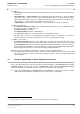
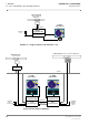

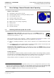
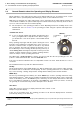
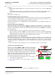
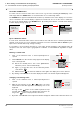
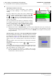
Table Of Contents
- General Safety Precautions
- List of Contents
- 1 Overview
- 2 Basic Settings; General Remarks about Operating
- 3 PPI Settings
- 3.1 Screen Stabilisation of the PPI: True Motion, Relative Motion
- 3.2 PPI Orientation: Head-Up, North-Up, Course-Up
- 3.3 Centering / Off-Centering of the Display (Center, Off-Center)
- 3.4 Range Selection (Range)
- 3.5 Range Rings, Grid
- 3.6 Own Ship Symbols and Target Symbols, Vectors, Past Position Plots
- 3.7 Trails
- 3.8 Setting the Display of Pre-planned Tracks
- 3.9 Defining the System Track and the Next Waypoint; System Track Display
- 3.10 Setting the Display of User Chart Objects on the RADARPILOT
- 3.11 Setting the Display of Charts and User Chart Objects on the CHARTRADAR
- 3.12 Setting the Display of the Map
- 3.13 Adjusting the Chart or Map to the Radar Video
- 4 Setting the Radar Function
- 4.1 Radar Function On/Off, Interswitch Functions, Master/Slave Switch-Over
- 4.2 Basic Setting of the Radar Video
- 4.3 Selection of the Antenna Revolution Rate
- 4.4 Radar Setting for High Speed of Own Vessel (HSC)
- 4.5 Radar Setting for the Display of RACON Codes
- 4.6 Radar Setting for SART Detection (X-Band only)
- 4.7 Suppression of the Synthetics and Video
- 5 Heading, Speed, Position
- 6 Bearing and Range
- 7 ARPA Functions
- 7.1 Symbols Used
- 7.2 Procedure of the Target Acquisition
- 7.3 Manual Target Acquisition
- 7.4 Automatic Target Acquisition; Settings of the Acquisition/Guard Zone
- 7.5 Deletion of Targets, Loss of Target
- 7.6 Target Data Display
- 7.7 Target Labels
- 7.8 Selecting the Reference Targets for Reference Target Tracking
- 8 EPA Functions (Electronic Plotting Aid)
- 9 Collision Avoidance (TCPA, CPA)
- 10 Trial Manoeuvres
- 11 Editing of Pre-planned Tracks
- 12 Editing the Map
- 13 Displays in the Multidisplay
- 14 Quick Info Box
- 15 Evaluation of the Radar Video
- 16 The Radar Keyboard
- 17 Alarm Management
- 18 List of Alarms
- 19 List of the Alarm Signal Outputs
- 20 Care and Maintenance Work
- 21 Performance Monitor
- 22 System Maintenance Manager
- 22.1 Determining the Versions of Software, Hardware and Documentation
- 22.2 Listing the System Faults
- 22.3 Off-Line Selfcheck
- 22.4 Checking / Correcting the Computer Time
- 22.5 Distribution and Deletion of Map Data; Data Saving
- 22.6 Exchanging Track Files between the Indicators; Data Saving
- 22.7 The Handling of Diskettes
- 22.8 Aborting and Restarting the Program of the Radar System

RADARPILOT / CHARTRADAR
ED 3038 G 232 / 01 (2002-06)
Operating Instructions
2 Basic Settings; General Remarks about Operating
2.2 General Remarks about the Operating and Display Elements
b_r1_e12.fm / 21.06.02
16
2.2 General Remarks about the Operating and Display Elements
On the indicators of the radar system, many screen display fields also act as switching areas or input
fields which can be operated quickly and intuitively by means of the trackball and cursor.
With these few elements, the entire radar system can be operated from the radar indicator with the aid
of its trackball. In addition, the optional radar keyboard contains function keys and rotary knobs for direct
access to some functions that are needed frequently.
☞ The description of the operating procedure in these Operating Instructions normally refers to the
trackball and cursor. In Section 16, the operating procedure using the optional radar keyboard is
summarised.
Trackball and Cursor
☞ If you are already familiar with graphic man-machine inter-
faces, you might be able to skip this section. Before doing so,
you should have a look at the picture of the trackball beside
this text.
Every operating step begins with the operator moving the cursor
by means of the trackball to a particular place on the screen (to a
text item, a numerical value, a symbol on the PPI or any desired
place on the PPI). The next step is always the pressing of one of
the trackball keys. In the following, this brief pressing of the key is
called clicking. What then happens depends on the key used, the
element on which clicking took place, and the operating situation,
and is the subject of these operating instructions.
The cursor has a resting position to which it goes 30 seconds after the last operating process. This
position is situated beside the PPI, below the ACQ TGT area.
If the cursor is situated outside the PPI, it is shaped like a hand or an arrow. Inside the PPI, it is a set of
crosswires.
The trackball has three keys with two different functions:
DO Key
The most important key is the middle (bigger) one. Almost all data areas react to this key, which performs
the functions that are needed the most frequently. In these operating instructions, it is called the "DO
key". In the following, "clicking" always means clicking with the DO key unless stated otherwise.
MORE Keys
The two keys situated above the DO key are called "MORE keys" in these operating instructions. They
have identical functions
1)
which are not needed as frequently. Not all elements which can be operated by
means of the DO key react to the MORE key also, and if they do, then always with functions other than
those of the DO key. Furthermore, by pressing of the MORE key, open menus (for menus, see below)
can generally be closed without any results, and inputs can be aborted.
Data Areas
Some data areas are used only to display numerical values, names or stati.
Example: Target data display
In the case of most data areas, the operating procedure for the functions displayed there is likewise
performed by clicking on the data area.
1)
There are two "MORE" keys so that both left-handed people and right-handed people can operate them ergonomically. Their functions are
identical.
DO key
MORE key...
for left-handed
people
for right-handed
people