
User's Manual
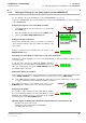

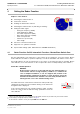

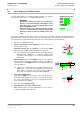
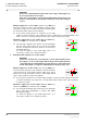
Table Of Contents
- General Safety Precautions
- List of Contents
- 1 Overview
- 2 Basic Settings; General Remarks about Operating
- 3 PPI Settings
- 3.1 Screen Stabilisation of the PPI: True Motion, Relative Motion
- 3.2 PPI Orientation: Head-Up, North-Up, Course-Up
- 3.3 Centering / Off-Centering of the Display (Center, Off-Center)
- 3.4 Range Selection (Range)
- 3.5 Range Rings, Grid
- 3.6 Own Ship Symbols and Target Symbols, Vectors, Past Position Plots
- 3.7 Trails
- 3.8 Setting the Display of Pre-planned Tracks
- 3.9 Defining the System Track and the Next Waypoint; System Track Display
- 3.10 Setting the Display of User Chart Objects on the RADARPILOT
- 3.11 Setting the Display of Charts and User Chart Objects on the CHARTRADAR
- 3.12 Setting the Display of the Map
- 3.13 Adjusting the Chart or Map to the Radar Video
- 4 Setting the Radar Function
- 4.1 Radar Function On/Off, Interswitch Functions, Master/Slave Switch-Over
- 4.2 Basic Setting of the Radar Video
- 4.3 Selection of the Antenna Revolution Rate
- 4.4 Radar Setting for High Speed of Own Vessel (HSC)
- 4.5 Radar Setting for the Display of RACON Codes
- 4.6 Radar Setting for SART Detection (X-Band only)
- 4.7 Suppression of the Synthetics and Video
- 5 Heading, Speed, Position
- 6 Bearing and Range
- 7 ARPA Functions
- 7.1 Symbols Used
- 7.2 Procedure of the Target Acquisition
- 7.3 Manual Target Acquisition
- 7.4 Automatic Target Acquisition; Settings of the Acquisition/Guard Zone
- 7.5 Deletion of Targets, Loss of Target
- 7.6 Target Data Display
- 7.7 Target Labels
- 7.8 Selecting the Reference Targets for Reference Target Tracking
- 8 EPA Functions (Electronic Plotting Aid)
- 9 Collision Avoidance (TCPA, CPA)
- 10 Trial Manoeuvres
- 11 Editing of Pre-planned Tracks
- 12 Editing the Map
- 13 Displays in the Multidisplay
- 14 Quick Info Box
- 15 Evaluation of the Radar Video
- 16 The Radar Keyboard
- 17 Alarm Management
- 18 List of Alarms
- 19 List of the Alarm Signal Outputs
- 20 Care and Maintenance Work
- 21 Performance Monitor
- 22 System Maintenance Manager
- 22.1 Determining the Versions of Software, Hardware and Documentation
- 22.2 Listing the System Faults
- 22.3 Off-Line Selfcheck
- 22.4 Checking / Correcting the Computer Time
- 22.5 Distribution and Deletion of Map Data; Data Saving
- 22.6 Exchanging Track Files between the Indicators; Data Saving
- 22.7 The Handling of Diskettes
- 22.8 Aborting and Restarting the Program of the Radar System

ED 3038 G 232 / 01 (2002-06)
Operating Instructions
4 Setting the Radar Function
4.1 Radar Function On/Off, Interswitch Functions, Master/Slave Switch-Over
b_r1_e22.fm / 21.06.02
47
RADARPILOT / CHARTRADAR
4 Setting the Radar Function
Subjects of this Section:
◆ Switching the radar function on
◆ Transceiver selection
◆ Defining the master/slave function
◆ Switching the radar function off (switching to stand-by)
◆ Setting the radar signal:
- Tuning the frequency (TUNE)
- Input amplification (GAIN)
- Sea clutter suppression (SEA)
- Rain clutter suppression (RAIN)
- Clean sweep function
- Interference rejection (IR)
-Pulse length
◆ Selection of antenna revolution rate
◆ Suppression of synthetics and video
◆ Special radar-settings (HSC, SART detection, RACON identification)
4.1 Radar Function On/Off, Interswitch Functions, Master/Slave Switch-Over
On any radar indicator, any transceiver of the system can be switched to act as the master. On the
master indicator, the radar is operated completely, i.e. both the transmitter side and the receiver side.
Any radar indicator can also be switched to act as a slave of any transceiver that is operating. On the
slave indicator, most of the functions on the reception side can be set independently of the master
1)
.
Switch-On of Radar Operation
DANGER:
At the instant of switch-on of the radar function, the antenna begins to
rotate and the emission of high frequency radiation
2)
is started. In the
case of multiple installations, it can also happen that, instead of the
expected antenna, a different one begins to rotate. Therefore, it must be
ensured beforehand that the antennas can rotate freely and that there is
nobody present close to the antenna turning circles.
The radar transceiver selected last is switched to radar operation by
clicking into the transceiver area and then clicking on the transceiver
designation that is displayed.
If the selected transceiver was already running in radar operation
mode, the result is that the indicator being operated becomes the
slave indicator.
3)
1)
Tuning, sea clutter suppression, pulse length (and also the antenna revolution rate) are defined only on the master indicator.
2)
For the danger posed by high frequency radiation, see page 4.
3)
A slave indicator is marked as such by the entry SLAVE behind the TUNE area.
1(X) ON
1.DO
2.DO
TX/ RX
STBY
--