
User's Manual

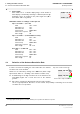
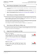
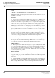
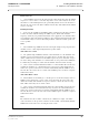


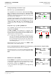
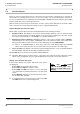
Table Of Contents
- General Safety Precautions
- List of Contents
- 1 Overview
- 2 Basic Settings; General Remarks about Operating
- 3 PPI Settings
- 3.1 Screen Stabilisation of the PPI: True Motion, Relative Motion
- 3.2 PPI Orientation: Head-Up, North-Up, Course-Up
- 3.3 Centering / Off-Centering of the Display (Center, Off-Center)
- 3.4 Range Selection (Range)
- 3.5 Range Rings, Grid
- 3.6 Own Ship Symbols and Target Symbols, Vectors, Past Position Plots
- 3.7 Trails
- 3.8 Setting the Display of Pre-planned Tracks
- 3.9 Defining the System Track and the Next Waypoint; System Track Display
- 3.10 Setting the Display of User Chart Objects on the RADARPILOT
- 3.11 Setting the Display of Charts and User Chart Objects on the CHARTRADAR
- 3.12 Setting the Display of the Map
- 3.13 Adjusting the Chart or Map to the Radar Video
- 4 Setting the Radar Function
- 4.1 Radar Function On/Off, Interswitch Functions, Master/Slave Switch-Over
- 4.2 Basic Setting of the Radar Video
- 4.3 Selection of the Antenna Revolution Rate
- 4.4 Radar Setting for High Speed of Own Vessel (HSC)
- 4.5 Radar Setting for the Display of RACON Codes
- 4.6 Radar Setting for SART Detection (X-Band only)
- 4.7 Suppression of the Synthetics and Video
- 5 Heading, Speed, Position
- 6 Bearing and Range
- 7 ARPA Functions
- 7.1 Symbols Used
- 7.2 Procedure of the Target Acquisition
- 7.3 Manual Target Acquisition
- 7.4 Automatic Target Acquisition; Settings of the Acquisition/Guard Zone
- 7.5 Deletion of Targets, Loss of Target
- 7.6 Target Data Display
- 7.7 Target Labels
- 7.8 Selecting the Reference Targets for Reference Target Tracking
- 8 EPA Functions (Electronic Plotting Aid)
- 9 Collision Avoidance (TCPA, CPA)
- 10 Trial Manoeuvres
- 11 Editing of Pre-planned Tracks
- 12 Editing the Map
- 13 Displays in the Multidisplay
- 14 Quick Info Box
- 15 Evaluation of the Radar Video
- 16 The Radar Keyboard
- 17 Alarm Management
- 18 List of Alarms
- 19 List of the Alarm Signal Outputs
- 20 Care and Maintenance Work
- 21 Performance Monitor
- 22 System Maintenance Manager
- 22.1 Determining the Versions of Software, Hardware and Documentation
- 22.2 Listing the System Faults
- 22.3 Off-Line Selfcheck
- 22.4 Checking / Correcting the Computer Time
- 22.5 Distribution and Deletion of Map Data; Data Saving
- 22.6 Exchanging Track Files between the Indicators; Data Saving
- 22.7 The Handling of Diskettes
- 22.8 Aborting and Restarting the Program of the Radar System

RADARPILOT / CHARTRADAR
ED 3038 G 232 / 01 (2002-06)
Operating Instructions
4 Setting the Radar Function
4.3 Selection of the Antenna Revolution Rate
b_r1_e22.fm / 21.06.02
52
9. Pulse length
After switch-over to a smaller display-range, check whether a
better display is obtained by switching to a different pulse length.
Switching is done by clicking on the pulse length area (SP =
Short Pulse, LP = Long Pulse).
Orientation values for settings on the open sea
Up to sea state 3 - 4, no rain
Gain 90% - 100%
Anticlutter sea 20%
Anticlutter rain 30%
Clean sweep OPEN SEA
Interference rejection On
Pulse length SP
Up to sea state 3 - 4, rain medium to heavy
Gain 85% - 95%
Anticlutter sea 20%
Anticlutter rain 50% - 60%
Clean sweep OPEN SEA
Interference rejection On
Pulse length SP or LP
Sea state 6 - 9, with rain
Gain 80% - 90%
Anticlutter sea 30% - 50%
Anticlutter rain 40% - 50%
Clean sweep OPEN SEA
Interference rejection On
Pulse length LP
4.3 Selection of the Antenna Revolution Rate
In order to increase the update rate of the radar video, the antenna
revolution rate can be doubled
1)
.
Switch-over is achieved by clicking on the HSC area (HSC = High
Speed Craft; "HSC on" = doubling of the antenna revolution rate).
☞ A disadvantage of the high revolution rate of the antenna is the
unavoidably higher rate of wear and tear on the antenna
gearbox.
☞ On vehicles classified as High Speed Craft, the high revolution
rate is a legal requirement. Therefore, on such vessels, the possibility of switching over to the lower
revolution rate is not provided.
1)
If the appropriate antenna gearbox is installed. Switching over is possible if the HSC area is present.
TX/ RX
1(X)
SP
DO
TX/ RX
1(X)
LP
DO
TX/ RX 1(X) SP HSC
TX/ RX
1(X) SP HSC
Coloured area = high revolution rat
Grey area = normal revolution rate