
User's Manual

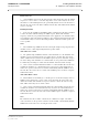


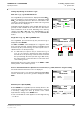
Table Of Contents
- General Safety Precautions
- List of Contents
- 1 Overview
- 2 Basic Settings; General Remarks about Operating
- 3 PPI Settings
- 3.1 Screen Stabilisation of the PPI: True Motion, Relative Motion
- 3.2 PPI Orientation: Head-Up, North-Up, Course-Up
- 3.3 Centering / Off-Centering of the Display (Center, Off-Center)
- 3.4 Range Selection (Range)
- 3.5 Range Rings, Grid
- 3.6 Own Ship Symbols and Target Symbols, Vectors, Past Position Plots
- 3.7 Trails
- 3.8 Setting the Display of Pre-planned Tracks
- 3.9 Defining the System Track and the Next Waypoint; System Track Display
- 3.10 Setting the Display of User Chart Objects on the RADARPILOT
- 3.11 Setting the Display of Charts and User Chart Objects on the CHARTRADAR
- 3.12 Setting the Display of the Map
- 3.13 Adjusting the Chart or Map to the Radar Video
- 4 Setting the Radar Function
- 4.1 Radar Function On/Off, Interswitch Functions, Master/Slave Switch-Over
- 4.2 Basic Setting of the Radar Video
- 4.3 Selection of the Antenna Revolution Rate
- 4.4 Radar Setting for High Speed of Own Vessel (HSC)
- 4.5 Radar Setting for the Display of RACON Codes
- 4.6 Radar Setting for SART Detection (X-Band only)
- 4.7 Suppression of the Synthetics and Video
- 5 Heading, Speed, Position
- 6 Bearing and Range
- 7 ARPA Functions
- 7.1 Symbols Used
- 7.2 Procedure of the Target Acquisition
- 7.3 Manual Target Acquisition
- 7.4 Automatic Target Acquisition; Settings of the Acquisition/Guard Zone
- 7.5 Deletion of Targets, Loss of Target
- 7.6 Target Data Display
- 7.7 Target Labels
- 7.8 Selecting the Reference Targets for Reference Target Tracking
- 8 EPA Functions (Electronic Plotting Aid)
- 9 Collision Avoidance (TCPA, CPA)
- 10 Trial Manoeuvres
- 11 Editing of Pre-planned Tracks
- 12 Editing the Map
- 13 Displays in the Multidisplay
- 14 Quick Info Box
- 15 Evaluation of the Radar Video
- 16 The Radar Keyboard
- 17 Alarm Management
- 18 List of Alarms
- 19 List of the Alarm Signal Outputs
- 20 Care and Maintenance Work
- 21 Performance Monitor
- 22 System Maintenance Manager
- 22.1 Determining the Versions of Software, Hardware and Documentation
- 22.2 Listing the System Faults
- 22.3 Off-Line Selfcheck
- 22.4 Checking / Correcting the Computer Time
- 22.5 Distribution and Deletion of Map Data; Data Saving
- 22.6 Exchanging Track Files between the Indicators; Data Saving
- 22.7 The Handling of Diskettes
- 22.8 Aborting and Restarting the Program of the Radar System

ED 3038 G 232 / 01 (2002-06)
Operating Instructions
5 Heading, Speed, Position
5.1 Compass
b_r1_e23.fm / 21.06.02
57
RADARPILOT / CHARTRADAR
5 Heading, Speed, Position
Subjects of this Section:
◆ Synchronisation of the gyro compass (Set Gyro)
◆ Selection of the speed sensor
◆ Specifying whether Speed Through the Water (STW) or Speed
Over Ground (SOG) is to be used
◆ Input for the Reference Target Speed mode
◆ Manual input of speed
◆ Input of drift and set
◆ Selection of the position sensor
◆ Manual correction of the position
CAUTION:
The right choice of navigation sensors, the right setting of the navigation
data and a continuous overview of the status of the selected navigation
sensors are very important for safe navigation.
In the case of multiple installations, the settings described in the following only have to be made on one
of the radar indicators. All components of the system are automatically supplied with the navigation data
resulting from the settings made on any desired radar indicator. This also applies to the CHARTPILOT,
if there is one.
5.1 Compass
For the transfer of the heading information, a technique is often used which transfers heading changes
only, and not the absolute value. Therefore, in such cases, after switch-on of the radar system and after
failure of the signal transfer, the synchronism of the heading transfer process must be checked and, if
necessary, corrected.
Display of the Heading Value Used
The heading value currently being transferred from the
compass and used in the entire radar system is displayed in
the HDG area.
Synchronisation of the Heading Transfer
Click on the Heading area and, by means of the virtual
keyboard, enter the value displayed by the gyro compass.
☞ If the ship is yawing, click on the OK button of the virtual keyboard when the heading displayed on
the compass has the same value as the value entered on the virtual keyboard.
If the course transfer takes place by means of a serial interface (e.g. according to IEC 61162), the
heading value cannot be changed.
HDG 45.6 °
GYRO
4 5 6
1 2 3
DO