
User's Manual

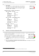
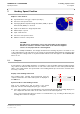

Table Of Contents
- General Safety Precautions
- List of Contents
- 1 Overview
- 2 Basic Settings; General Remarks about Operating
- 3 PPI Settings
- 3.1 Screen Stabilisation of the PPI: True Motion, Relative Motion
- 3.2 PPI Orientation: Head-Up, North-Up, Course-Up
- 3.3 Centering / Off-Centering of the Display (Center, Off-Center)
- 3.4 Range Selection (Range)
- 3.5 Range Rings, Grid
- 3.6 Own Ship Symbols and Target Symbols, Vectors, Past Position Plots
- 3.7 Trails
- 3.8 Setting the Display of Pre-planned Tracks
- 3.9 Defining the System Track and the Next Waypoint; System Track Display
- 3.10 Setting the Display of User Chart Objects on the RADARPILOT
- 3.11 Setting the Display of Charts and User Chart Objects on the CHARTRADAR
- 3.12 Setting the Display of the Map
- 3.13 Adjusting the Chart or Map to the Radar Video
- 4 Setting the Radar Function
- 4.1 Radar Function On/Off, Interswitch Functions, Master/Slave Switch-Over
- 4.2 Basic Setting of the Radar Video
- 4.3 Selection of the Antenna Revolution Rate
- 4.4 Radar Setting for High Speed of Own Vessel (HSC)
- 4.5 Radar Setting for the Display of RACON Codes
- 4.6 Radar Setting for SART Detection (X-Band only)
- 4.7 Suppression of the Synthetics and Video
- 5 Heading, Speed, Position
- 6 Bearing and Range
- 7 ARPA Functions
- 7.1 Symbols Used
- 7.2 Procedure of the Target Acquisition
- 7.3 Manual Target Acquisition
- 7.4 Automatic Target Acquisition; Settings of the Acquisition/Guard Zone
- 7.5 Deletion of Targets, Loss of Target
- 7.6 Target Data Display
- 7.7 Target Labels
- 7.8 Selecting the Reference Targets for Reference Target Tracking
- 8 EPA Functions (Electronic Plotting Aid)
- 9 Collision Avoidance (TCPA, CPA)
- 10 Trial Manoeuvres
- 11 Editing of Pre-planned Tracks
- 12 Editing the Map
- 13 Displays in the Multidisplay
- 14 Quick Info Box
- 15 Evaluation of the Radar Video
- 16 The Radar Keyboard
- 17 Alarm Management
- 18 List of Alarms
- 19 List of the Alarm Signal Outputs
- 20 Care and Maintenance Work
- 21 Performance Monitor
- 22 System Maintenance Manager
- 22.1 Determining the Versions of Software, Hardware and Documentation
- 22.2 Listing the System Faults
- 22.3 Off-Line Selfcheck
- 22.4 Checking / Correcting the Computer Time
- 22.5 Distribution and Deletion of Map Data; Data Saving
- 22.6 Exchanging Track Files between the Indicators; Data Saving
- 22.7 The Handling of Diskettes
- 22.8 Aborting and Restarting the Program of the Radar System

RADARPILOT / CHARTRADAR
ED 3038 G 232 / 01 (2002-06)
Operating Instructions
5 Heading, Speed, Position
5.3 Position Sensor
b_r1_e23.fm / 21.06.02
60
5.3 Position Sensor
There are often several position sensors connected to the system. One of them has to be selected. As
an alternative to selecting a position sensor, it can - if necessary - also be specified that the system posi-
tion is to be determined on the radar by dead reckoning (EP = Estimated Position) using the gyro heading
and the speed data of the selected speed sensor.
After the position sensor has been selected, the accuracy of the position data must be checked continu-
ously. Constant errors in the transferred position can be compensated manually.
General Remarks about Position Data
On the radar, it is basically necessary to distinguish between the following positions:
1. System position: The display is shown in the position display when the cursor is situated outside
the PPI. "System position" is normally defined as a position in the forward part of the ship - usually
the location of the transducer of the DOLOG or of another installed log.
2. Reference position for bearings: All displays relating to own position (own ship symbol, VRM/EBL,
range/bearing of the cursor position, CPA/TCPA) refer to the antenna position of the radar that is
being operated. This is made clear in the Position Display by the entry REF RADAR.
☞ There is no LAT/LON display of this position, but in the small display-ranges the LAT/LON
values can be read off as the cursor position if the cursor is moved to the radar origin.
3. Cursor position: The display is shown in the position display when the cursor is situated within the
PPI. This display indicates the absolute geographical position.
All LAT/LON values are based on the geodetic datum "WGS 84".
☞ Important: Only position receivers may be connected to the radar system that output the position
values in the geographical reference system WGS 84 via an interface as per IEC 61162-1
1)
.
Display of the Position Data Used
In the Position Display, the position data used in the system
are displayed:
-Behind POS: the selected position sensor.
-Behind LAT and LON: the system position.
-Behind COG and SOG: the values of course and speed
over ground that are transferred from the selected speed
sensor.
-Behind ADJUST: the value of the manual position-correc-
tion in metres N/S and W/E,
☞ If a manual position-correction has been entered, the LAT
and LON values have a yellow background.
1)
IEC 61162-1 largely corresponds to NMEA 0183 Version 2.30 of 1st March 1998.
POS
LAT
LON
COG
SOG
55:35. 285 N
008:36.437 W
51.6 °
18.3 kt
GPS1
ADJUST
–– – ––
–– – ––
REF
RADAR