
User's Manual
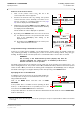
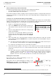
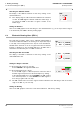


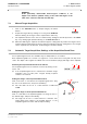
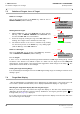
Table Of Contents
- General Safety Precautions
- List of Contents
- 1 Overview
- 2 Basic Settings; General Remarks about Operating
- 3 PPI Settings
- 3.1 Screen Stabilisation of the PPI: True Motion, Relative Motion
- 3.2 PPI Orientation: Head-Up, North-Up, Course-Up
- 3.3 Centering / Off-Centering of the Display (Center, Off-Center)
- 3.4 Range Selection (Range)
- 3.5 Range Rings, Grid
- 3.6 Own Ship Symbols and Target Symbols, Vectors, Past Position Plots
- 3.7 Trails
- 3.8 Setting the Display of Pre-planned Tracks
- 3.9 Defining the System Track and the Next Waypoint; System Track Display
- 3.10 Setting the Display of User Chart Objects on the RADARPILOT
- 3.11 Setting the Display of Charts and User Chart Objects on the CHARTRADAR
- 3.12 Setting the Display of the Map
- 3.13 Adjusting the Chart or Map to the Radar Video
- 4 Setting the Radar Function
- 4.1 Radar Function On/Off, Interswitch Functions, Master/Slave Switch-Over
- 4.2 Basic Setting of the Radar Video
- 4.3 Selection of the Antenna Revolution Rate
- 4.4 Radar Setting for High Speed of Own Vessel (HSC)
- 4.5 Radar Setting for the Display of RACON Codes
- 4.6 Radar Setting for SART Detection (X-Band only)
- 4.7 Suppression of the Synthetics and Video
- 5 Heading, Speed, Position
- 6 Bearing and Range
- 7 ARPA Functions
- 7.1 Symbols Used
- 7.2 Procedure of the Target Acquisition
- 7.3 Manual Target Acquisition
- 7.4 Automatic Target Acquisition; Settings of the Acquisition/Guard Zone
- 7.5 Deletion of Targets, Loss of Target
- 7.6 Target Data Display
- 7.7 Target Labels
- 7.8 Selecting the Reference Targets for Reference Target Tracking
- 8 EPA Functions (Electronic Plotting Aid)
- 9 Collision Avoidance (TCPA, CPA)
- 10 Trial Manoeuvres
- 11 Editing of Pre-planned Tracks
- 12 Editing the Map
- 13 Displays in the Multidisplay
- 14 Quick Info Box
- 15 Evaluation of the Radar Video
- 16 The Radar Keyboard
- 17 Alarm Management
- 18 List of Alarms
- 19 List of the Alarm Signal Outputs
- 20 Care and Maintenance Work
- 21 Performance Monitor
- 22 System Maintenance Manager
- 22.1 Determining the Versions of Software, Hardware and Documentation
- 22.2 Listing the System Faults
- 22.3 Off-Line Selfcheck
- 22.4 Checking / Correcting the Computer Time
- 22.5 Distribution and Deletion of Map Data; Data Saving
- 22.6 Exchanging Track Files between the Indicators; Data Saving
- 22.7 The Handling of Diskettes
- 22.8 Aborting and Restarting the Program of the Radar System

RADARPILOT / CHARTRADAR
ED 3038 G 232 / 01 (2002-06)
Operating Instructions
6 Bearing and Range
6.3 Electronic Bearing Lines (EBL’s)
b_r1_e24.fm / 21.06.02
64
Switching the VRM On and Off
The display of the VRM is switched on and off by clicking on the
desired VRM area.
☞ If the display range is reduced when the VRM is in the switched-
on state, the VRM might be situated outside the visible range. If
you switch the VRM off and then on again, it returns to the
visible range.
Setting the Distance
Click on the VRM graphics in the PPI, drag it to the desired distance (e.g. to the object whose range is
to be measured). The VRM is fixed by clicking again.
6.3 Electronic Bearing Lines (EBL’s)
The radar has two EBL’s, which can be adjusted independently of
one another. With these EBL's, the bearing of an object with respect
to own ship or the bearing between two objects can be determined.
An EBL that is switched on can be recognised from the fact that the
bearing is displayed in the left-hand EBL-area. An EBL that is
switched off is indicated by the word OFF in that area.
Switching the EBL On and Off
The display of the EBL is switched on and off by clicking on the
desired EBL data area.
Setting the Origin of the EBL
For the bearing with respect to own ship:
Select CENTER in the right-hand EBL-area.
For the bearing between two objects:
To set the EBL origin to a different position, in the PPI click on
the EBL origin and position it at the desired place by clicking.
In the right-hand EBL-area, select FIX ABS if the EBL origin is
to be at a fixed position, or select FIX REL if the EBL origin is to
move along together with own ship.
☞ The EBL remains intact even if the origin is situated outside the PPI. Switching on and off resets the
origin of the EBL to your own ship.
Setting the Bearing
Click on the EBL graphics in the PPI, set the desired direction, and fix it by clicking.
1
2.00 NM
1
OFF
DO
VRM
EBL
CENTER
1
T
CENTER
2
T
122.7 °
OFF
CENTER
1
T
OFF
CENTER
1
T
122.7 °
DO
1.DO
2.DO
CENTER
1
T
122.7 °
FIX ABS
FIX REL
CENTER