Inverter Installation Kit DC-1000-KIT DC-2000-KIT DC-2500-KIT DC-3500-KIT Owner's Manual Please read this manual before installing your DC Inverter Installation Kit
Owner's Manual | Index Section 1 Important Safety Precautions................................................. 3 Section 2 General ............................................................................ 4 Section 3 Installation Instructions .......................................................... 7 Section 4 Specifications ...................................................................... 13 Section 5 Warranty 2 | SAMLEX AMERICA INC. .......................................................
Section 1 | Important Safety Precautions ! Installation and wiring compliance Installation and wiring must comply with the local and National Electrical Codes and must be done by a certified electrician. Preventing Fire and Explosion Hazards Working with the inverter may produce arcs or sparks. Thus, the inverter should not be used in areas where there are inflammable materials or gases requiring ignition protected equipment.
Section 2 | General The Inverter Installation Kit consists of two cables and fuse arrangement for connecting the battery to the inverter in a safe manner. Fuse Protection in the Battery Circuit A battery is an unlimited source of current. Under short circuit conditions, a battery can supply thousands of Amperes of current.
Section 2 | General The size (thickness / cross-section) of the conductors is designated by AWG (American Wire Gauge). Please note that a smaller AWG # denotes a thicker size of the conductor up to AWG #1. Wires thicker than AWG #1 are designated AWG #1/0, AWG #2/0, AWG #3/0 and so on. In this case, increasing AWG # X/0 denotes thicker wire. DC input circuit of an inverter is required to handle very large DC currents.
Section 2 | General Characteristics of the Cable Provided with the Kits We have provided the highest quality, industrial / welding grade, flexible cable with the Kits. These cables are designed for use as motor and power leads where flexibility and portability are required. The inherent nature of the design makes the cables suitable for battery cables for automotive and renewable energy applications.
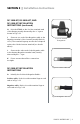
Section 3 | Installation Instructions DC-1000-KIT, DC-2000-KIT, AND DC-2500-KIT INSTALLATION INSTRUCTIONS Preparing Cable Termination for Inverter End • The cables provided in the kits have copper ring terminals on both the ends. • The ring terminal may not fit the DC input terminal on the inverter and may need to be reshaped / replaced with cable lugs provided with the inverter. • Some inverters require Pin Type of terminal lugs to fit DC input connectors with a cylindrical hole and set screw.
Section 3 | Installation Instructions Fig. 3.5. M-8 Nut, Flat Washer and Spring Washer Fig. 3.8. Fig. 3.9. MRBF Fuse and Positive cable fixed to the CFBAR Fig. 3.6. Insulating cap Fig. 3.10. Insulating Cap slid over the rectangular portion of CFBAR Fig. 3.7. MRBF Fuse inserted onto the stud on CFBAR Fig. 3.11. CFBAR with fitted fuse MRBF 8 | SAMLEX AMERICA INC.
Section 3 | Installation Instructions DC-1000-KIT, DC-2000-KIT, AND DC-2500-KIT INSTALLATION INSTRUCTIONS (continued) H. Bolt the CFBAR to the Positive terminal stud of the Battery usually denoted by the ‘+’ sign as shown in Fig. 3.12. I. Connect one end of the Negative cable to the Negative terminal of the inverter (usually Black in color). The terminal lug may need to be reshaped/ replaced to fit the inverter terminal (see details above). Fig. 3.12. Installed arrangement J.
Section 3 | Installation Instructions DC-3500-KIT INSTALLATION INSTRUCTIONS (continued) B. The Class T Fuse Assembly (Fig. 3.15) consists of the following components assembled as one unit: Class T Fuse – Fig. 3.16: This is rated at 125V, 400A. It is UL Class “T” rated and UL listed as per UL Standard 248-15. It has AIC (Ampere Interrupting Capacity) of 20,000A Fig. 3.15. Class “T” Fuse Assembly Fuse Holder – Fig. 3.
Section 3 | Installation Instructions Fig. 3.18. Battery end of Positive cable cut and prepared for inserting into the Class “T” Fuse Assembly Fig. 3.19. Fitted Class “T” Fuse Assembly NOTE: The diameter of the hole in the screw down terminal for the cable entry is 0.6” and is just big enough for the diameter of the bare AWG #4/0 stranded cable.
Section 3 | Installation Instructions DC-3500-KIT INSTALLATION INSTRUCTIONS (continued) E. Connect the terminal lug of the shorter section of the cut Positive cable to the Positive terminal of the Battery, usually denoted by the ‘+’ sign (see Fig. 3.20). F. Connect the terminal lug of the longer section of the cut Positive cable to the Positive terminal of the inverter (usually Red in color). The terminal lug may need to be reshaped/replaced to fit the inverter terminal (see details above). G.
Section 4 | Specifications Model † Cable Size DC-1000-KIT DC-2000-KIT DC-2500-KIT DC-3500-KIT AWG #4 AWG #2 AWG #2/0 AWG #4/0 Battery System Voltage Length of Cable Run 12V System 3 ft. 1.3 % 1.6 % 1.2 % 1.0 % 6 ft. 2.5 % 3.2 % 2.3 % 2.0 % 10 ft. 4.2 % 5.3 % 3.9 % 3.3 % 3 ft. 0.6 % 0.8 % 0.6 % 0.5 % 6 ft. 1.3 % 1.6 % 1.2 % 1.0 % 10 ft. 2.1 % 2.7 % 1.9 % 1.
Section 4 | Specifications NOTES *• • • • • • • • Current in Amperes a conductor can carry continuously under conditions of use without exceeding its temperature rating is termed Ampacity (Ampere Capacity). Conductor temperature rating of 105°C / 221°F, ambient temperature of 30°C / 86°F and wiring in free air have been considered. Cable size is indicated in American Wire Gauge (AWG). AWG of a stranded cable is determined by the total cross-sectional area of the conductors.
SECTION 5 | Warranty 2 Year limited warranty Samlex Inverter Installation Kits manufactured by Samlex America, Inc. (the “Warrantor“) are warranted to be free from defects in workmanship and materials under normal use and service. The warranty period is 2 years for the United States and Canada, and is in effect from the date of purchase by the user (the “Purchaser“). Warranty outside of the United States and Canada is limited to 6 months.
Contact Information Toll Free Numbers Ph: 800 561 5885 Fax: 888 814 5210 Local Numbers Ph: 604 525 3836 Fax: 604 525 5221 Website www.samlexamerica.com USA Shipping Warehouse Kent WA Canadian Shipping Warehouse Delta BC Email purchase orders to orders@samlexamerica.
Kit D’installation De L’onduleur DC-1000-KIT DC-2000-KIT DC-2500-KIT DC-3500-KIT Guide D’utilisation Veuillez consulter ce guide avant d’utiliser votre Kit d’installation de l’onduleur
GUIDE D’UTILISATION | Indice Section 1 Consignes de sécurité............................................................ 3 Section 2 Général ............................................................................ 4 Section 3 Instructions d’installation....................................................... 7 Section 4 Spécifications ...................................................................... 13 Section 5 Garantie 2 | SAMLEX AMERICA INC. ...............................................
Section 1 | Consignes de sécurité ! Installation et conformité des câbles L’installation et le branchement doivent êtres conformes aux normes électriques locales et nationales américaines (NEC) et doivent être effectués par un électricien certifié. Prévention des risques d’incendie et d’explosion L’utilisation de l’onduleur peut provoquer des arcs électriques ou des étincelles.
Section 2 | Général Protection des fusibles dans le circuit de batteries Une batterie est une source illimitée de courant. Lors de courts circuits, une batterie peut fournir des milliers d’Ampères de courant. S’il y a un court circuit sur la longueur des câbles connectant la batterie à l’onduleur, des milliers d’Ampères de courant seraient produit. Le câble sera en surchauffe et l’isolation finira par briser.
Section 2 | Général La taille (épaisseur/intersection) des conducteurs est régler par le AWG (American Wire Gauge). Veuillez noter qu’un plus petit AWG indique que le conducteur est d’une taille plus épaisse, jusqu’à AWG #1. Les câbles plus épais que l’AWG #1 sont désignés par AWG #1/0, AWG #2/0, AWG #3/0 et ainsi suite. Dans ce cas, l’augmentation de AWG # X/0 indique que le câble est plus épais. Le circuit d’entrée CC d’un onduleur doit supporter des courants CC très puissants.
Section 2 | Général la chute de tension à moins de 5%. Coupez la longueur restante du câble, si la distance entre la batterie et l’onduleur est inferieur à 3 mètres. Caractéristiques du câble fourni dans les kits Nous avons intégré au kit, un câble de haute qualité, de type industriel, très flexible. Ces câbles sont conçus pour être utilisés comme moteurs et générateurs de courant, lorsque la flexibilité et la portabilité sont requises.
Section 3 | Instructions d’ installation INSTRUCTIONS D’INSTALLATION POUR LE DC-1000-KIT, DC-2000-KIT ET DC-2500-KIT Préparation de la terminaison des câbles pour les bornes de l’onduleur : • Les câbles fournis dans les kits contiennent des cosses en cuivre aux deux extrémités. • La cosse n’est pas forcément adaptée à la borne d’entrée cc de l’onduleur et il se peut que les câbles doivent être remodelés ou remplacés par des cosses de câble fournies avec l’onduleur.
Section 3 | Instructions d’installation Fig. 3,5. Écrou M-8, rondelle plate, rondelle élastique Fig. 3,8 Fig. 3,9. Fusible MRBF et câble positif fixé sur le CFBAR Fig. 3,6. Capuchon isolant Fig. 3,10. Capuchon isolant glissé sur la bande rectangulaire de la CFBAR Fig. 3,7. Fusible MRBF posé sur la gaine de la CFBAR Fig. 3,11. CFBAR avec le fusible MRBF installé 8 | SAMLEX AMERICA INC.
Section 3 | Instructions d’installation INSTRUCTIONS D’INSTALLATION POUR LE DC-1000-KIT, DC-2000-KIT ET DC-2500-KIT (SUITE) G. Faites glisser le capuchon isolant sur la bande rectangulaire de la CFBAR et pliez- le pour couvrir la gaine exposée de la CFBAR. Voir les figures 3,10 et 3,11. H. Boulonnez la CFBAR à la borne positive de la batterie normalementt marquée avec le signe « + », montré sur la Fig, 3,12. Fig. 3,12. Dispositif installé I.
Section 3 | Instructions d’installation INSTRUCTIONS D’INSTALLATION DU KIT-CC-3500 (SUITE) B. L’assemblage de fusible classe “T” (Fig. 3,15.) se compose des pièces suivantes assemblées en un seul unité : Fusible classe “T” – Fig. 3,16 : Ce fusible est classé a 125V, 400A, Il est de la classe UL « T » et est listé par la norme UL 248-15, Il est disposé d’une CIA (Capacité d’Interruption d’Ampère) de 20,000A. Porte fusible – Fig.
Section 3 | Instructions d’installation Fig. 3,18. Extrémité du câble positif de la batterie découpé et préparé pour insertion dans l’assemblage de fusible classe “T” Fig. 3,19. Assemblage de fusible classe“T” Le diamètre du trou dans le bornier à vis pour l’entrée du câble est 15mm et qui est juste assez grand pour le diamètre de la terminason dénudée du câble d’une taille de AWG #4/0.
Section 3 | Instructions d’installation INSTRUCTIONS D’INSTALLATION DU KIT-CC-3500 (SUITE) e. Connectez la cosse de la section la plus courte du câble positif découpé à la borne positive de la batterie, normalement marquée avec le signe « + » (voir Fig. 3,20). F. Connectez la cosse de la section la plus longue du câble positif découpé à la borne positive de l’onduleur (normalement de couleur rouge).
Section 4 | Spécifications Modèle DC-1000-KIT DC-2000-KIT DC-2500-KIT DC-3500-KIT † Taille de Câble AWG #4 AWG #2 AWG #2/0 AWG #4/0 Tension de Système de Batterie Longueur du Parcours de Câble Système 12V 90 cm 1,3 % 1,6 % 1,2 % 1,0 % 1,80 m 2,5 % 3,2 % 2,3 % 2,0 % 3m 4,2 % 5,3 % 3,9 % 3,3 % 90 cm 0,6 % 0,8 % 0,6 % 0,5 % 1,80 m 1,3 % 1,6 % 1,2 % 1,0 % 3m 2,1 % 2,7 % 1,9 % 1,7 % MRBF-100 100 Amp MRBF-200 200 Amp MRBF-300
Section 4 | Spécifications Remarques • Le courant en Ampères qu’un conducteur peut transmettre continuellement sous des conditions de service sans excedé sa température de fonctionnement est appelé le Courant Admissible. La température de fonctionnement du Conducteur est de 105°C / 221°F, la température ambiante de 30°C / 86°F et le câblage à l’air libre est consideré. La taille de câble est indiqué par la Jauge Américaine de Fils (AWG).
SECTION 5 | Garantie GARANTIE LIMITÉE DE 2 ANS KITS D’INSTALLATION DE L’ONDULEUR, fabriqués par Samlex America, Inc. (le « Garant ») sont garantis d’être non défectueux dans la conception et dans les matériaux, moyennant une utilisation et un service normaux. La période de la garantie est de 2 ans aux États-Unis et au Canada, et prend effet le jour de l’achat par l’utilisateur (« l’Acheteur »). La garantie hors des États Unis et du Canada est limitée à 6 mois.
Information de Contact Numéros gratuits Tel : 1 800 561 5885 Fax : 1 888 814 5210 Numéros locaux Tel : 604 525 3836 Fax : 604 525 5221 Site internet www.samlexamerica.com Entrepôt aux ÉU Kent, WA Entrepôt au Canada Delta, BC Adresse email pour passer une commande orders@samlexamerica.