
Product Manual


10 | SAMLEX AMERICA INC.
DC-3500-KIT INSTALLATION
INSTRUCTIONS (continued)
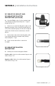
B. The Class T Fuse Assembly (Fig. 3.15)
consists of the following components
assembled as one unit:
Class T Fuse – Fig. 3.16: This is rated at 125V,
400A. It is UL Class “T” rated and UL listed as
per UL Standard 248-15. It has AIC (Ampere
Interrupting Capacity) of 20,000A
Fuse Holder – Fig. 3.17: This consists of a
breglass insulated base with studs / bolts
(5/16” diameter, 18 Threads Per Inch) and
nuts (requires ½” size wrench) for holding
the fuse. The two terminals for cable entry
are designed for #4/0 cable (Hole size is
0.6” / 15.5 mm). Hexagonal headed socket
screws (requires Allen Key size 5/16”) are
used to clamp the cable ends.
Snap on cover : Made of clear polycarbonate
and provides touch safety.
C. The fuse should normally be installed
within 7 inches of the Positive Terminal of
the battery. Cut the Positive cable based on
the desired location of the Class “T” Fuse
Assembly using an appropriate wire cutter.
Strip 1.05” of the insulation at the cut
ends using a suitable wire stripper. Please
ensure that the innermost layer of the tape
separator is completely removed.
See Fig. 3.18.
D. Insert the bare ends of the cable into
the hole for the cable entry and tighten
the screw down terminals rmly. Fix the
clear polycarbonate snap on cover for touch
safety. See Fig. 3.19.
Fig. 3.15. Class “T” Fuse Assembly
Fig. 3.16. Class “T” Fuse
Fig. 3.17. Fuse Holder
SECTION 3 | Installation Instructions