
Product Manual

12 | SAMLEX AMERICA INC.
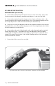
E. Connect the terminal lug of the shorter section of the cut Positive cable to the
Positive terminal of the Battery, usually denoted by the ‘+’ sign (see Fig. 3.20).
F. Connect the terminal lug of the longer section of the cut Positive cable to the
Positive terminal of the inverter (usually Red in color). The terminal lug may need to
be reshaped/replaced to t the inverter terminal (see details above).
G. Connect one end of the Negative cable to the Negative terminal of the inverter
(usually Black in color). The terminal lug may need to be reshaped/replaced to t the
inverter terminal (see details above).
H. Connect the other end of the Negative cable to the battery Negative terminal,
usually denoted by the ‘-’ sign. When the lug of the Negative cable rst makes
contact with the Negative terminal of the battery, a spark may be observed. This is
normal. This spark occurs because of the initial charging current of the input side
capacitors inside the inverter.
I. Ensure that all the connections are tight.
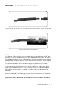
Fig. 3.20. Positive cable connection to the battery – with Class “T” Fuse Assembly
DC-3500-KIT INSTALLATION
INSTRUCTIONS (continued)
SECTION 3 | Installation Instructions