
Product Manual


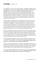


8 | SAMLEX AMERICA INC. SAMLEX AMERICA INC. | 9
DC-1000-KIT, DC-2000-KIT, AND
DC-2500-KIT INSTALLATION
INSTRUCTIONS (continued)
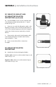
H. Bolt the CFBAR to the Positive terminal stud
of the Battery usually denoted by the ‘+’ sign as
shown in Fig. 3.12.
I. Connect one end of the Negative cable to the
Negative terminal of the inverter (usually Black in
color). The terminal lug may need to be reshaped/
replaced to t the inverter terminal (see details
above).
J. Connect the other end of the Negative cable
to the battery Negative terminal stud, usually
denoted by the ‘-’ sign.
K. Please ensure that all the connections
are tight.
DC-3500-KIT INSTALLATION
INSTRUCTIONS
A. Identify the Positive & Negative Cables:
Positive cable: Red color with terminal lugs at each
end as in Fig. 3.13.
Negative cable: Black color with terminal lugs at
each end as in Fig. 3.14.
Fig. 3.12. Installed
arrangement
Fig. 3.13. Positive cable end
Fig. 3.14. Negative cable end
SECTION 3 | Installation Instructions