
Samlex EVO Series Manual

40 | SAMLEX AMERICA INC.
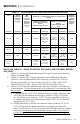
4) Column 9 indicates the size of external fuse in the battery circuit. It is
mandatory to install this fuse within 7” of the battery Positive terminal to
protect the internal DC Input Section of the unit and also to protect the
battery cables against short circuit. Amp rating of the fuse is based on the
following considerations:
a) Not less than NEC Ampacity of 125% of the Rated Continuous DC Input
Current (Column 3) - Refer to NEC-2014 (National Electrical Code) -
Section 215.3
b) Closest Standard Ampere Rating of Fuse has been used - Refer to NEC-2014
(National Electrical Code) - Section 240.6(A)
c) Where Standard Fuse Rating does not match the required Ampacity of
125% of the Rated Continuous DC Input Current (Column 3), the next
higher Standard Rating of the fuse has been used - Refer to NEC-2014
(National Electrical Code) - Section 240.4(B)
d) Type of fuse: Fast-acting, Current Limiting, UL Class T (UL Standard 248-15)
or equivalent
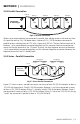
3.5.7 Using Proper DC Cable Termination
The battery end and the inverter end of the wires should have proper terminal lugs that will
ensure a rm and tight connection. Choose lugs to t the wire size and the stud sizes on the
inverter and battery ends.
3.5.8 Reducing RF Interference
To reduce the effect of radiated interference, shield the wires with sheathing / copper foil /
braiding. For details, refer to Limiting Electro-Magnetic Interference" at Section 1.3.4.
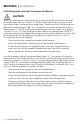
3.5.9 Taping Battery Wires Together To Reduce Inductance
Do not keep the battery wires far apart. Keep them taped together to reduce their inductance.
Reduced inductance of the battery wires helps to reduce induced voltages. This reduces ripple in the
battery wires and improves performance and efciency. For details, refer to Limiting Electro-Magnetic
Interference" at Section 1.3.4.
SECTION 3 | Installation