
Samlex IDC-100A-12 Manual

DC-DC Converter Manual | 1
IDC-100
USER MANUAL
Head Ofce
103 - 4268 Lozells Avenue
Burnaby, BC V5A 0C6 Canada
Toll Free Numbers
Ph: 1-800-561-5885
Fax: 1-888-814-5210
Local Numbers
Ph: 604-525-3836
Fax: 604-525-5221
DESCRIPTION, FEATURES & APPLICATIONS
IDC-100 is an Isolated DC-DC Converter series covering wide range of DC input voltages of 12V/24V/48V and outputs of 12V/24V. Design features
include:
-
Advanced Switch Mode T
echnology with xed frequency PWM control for optimum efciency and reliability and compact size
-
Galvanic isolation between input and output sides with following benets:
-
Noise on the input side is isolated fr
om the output side for noise sensitive loads like radios, instrumentation, data processing etc.
-
Converts Positive voltage to Negative voltage with r
espect to common, non-insulated ground. For example, IDC-100C-12 can convert - 48VDC
of telecom supply to +12VDC supply
-
Can be used to cr
eate either Negative isolated or Positive isolated Rail using single unit or dual Positive and Negative isolated Rails using 2
units in series.
-
Pr
otections against short circuit/overload, input over voltage/transients, output over voltage, over heating and reverse polarity;
-
Compliance with Eur
opean EMI/EMC and Automotive Standards
Applications include noise sensitive loads like radios, instrumentation and data processing for isolated input and output grounds and telecom,
tractor trailers, buses, forklifts, heavy machinery, locomotive/railroad, marine and aviation for non-isolated, common input and output ground.
INSTALLATION & OPERATION
WARNING! This unit is NOT a Battery Charger. Please do not use to charge a battery.
General Installation Requirements
- The unit is cooled by a temperature controlled fan. Install the unit in a cool, dry and well ventilated space. Do not block fan vent openings on
the sides.
-
Do not install the unit inside engine compartment.
-
Do not connect/disconnect input and output connections when live voltages are present.
For more information on input / output grounding e.g. installation on Positive Grounding System, refer to www.samlexamerica.com under:
Support Ò Application Notes Ò DC-DC Converters − Input and Output Grounding.
Fusing on the Input & Output Sides
The input side of the unit will be connected to the battery. A battery has the capacity to supply very large currents. In case there is a short circuit between
the input side wiring, very heavy current will ow and will burn/melt the wiring and may be a re hazard. To prevent this, use a suitable fast blow fuse
(see Table 1) in line with the Positive input wire within 7" from the battery Positive terminal. The output side should be connected through a suitable fuse
in line with the "Output +" terminal (see Table 2).
WARNING! The Warranty will be voided if proper fuse is not used as recommended.
Switching ON & Switching OFF Arrangement on the Input Side
There is no ON/OFF switch on the input side of the unit. An external ON/OFF switch may be used in series with the Positive input wire, if required.
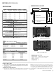
Sizing of Input and Output Wiring
In order to prevent excessive voltage drop and consequent loss of current capacity and efciency, use proper size of input and output wires. Please
note that as the current/length of wiring are increased, the thickness of the wiring will also be required to be increased. The thickness of wires and
cables is normally expressed in AWG (American Wire Gauge). Also, note that a lower AWG number denotes a thicker wire. Use multi-stranded
copper insulated wiring rated for at least 90C/194F. Please refer to details of input/output wire sizes (Tables 1 and 2).