Solar Charge Controller MSK-10A Owner's Manual Please read this manual before using your Solar Charge Controller.
Owner's Manual | Index Section 1 Safety Instructions.................................................................. 3 Section 2 General Information, Features & Layout ............................... 5 Section 3 Installation ............................................................................ 7 Section 4 Operation ......................................................................... 13 Section 5 Protections, Troubleshooting & Maintenance ......................
Section 1 | Safety Instructions IMPORTANT SAFETY INSTRUCTIONS PLEASE READ THE FOLLOWING SAFETY INSTRUCTIONS BEFORE USING THE CHARGE CONTROLLER. FAILURE TO ABIDE BY THE RECOMMENDATIONS MAY CAUSE PERSONAL INJURY / DAMAGE TO THE CONTROLLER. The following safety symbols will be used in this manual to highlight safety and information: WARNING! Indicates possibility of physical harm to the user in case of non-compliance. ! i CAUTION! Indicates possibility of damage to the equipment in case of non-compliance.
SECTION 1 | Safety Instructions 11. When charging, removal of the battery from the vehicle is not necessary provided the battery is being charged in a well-ventilated area. 12. Batteries contain very corrosive diluted Sulphuric Acid as electrolyte. Precautions should be taken to prevent contact with skin, eyes or clothing. If the battery acid makes contact with skin or clothing, flush immediately with water. See a doctor immediately. 13.
Section 2 | General Information, Features & Layout MSK-10A is a 10A rated, Series Type of PWM (Pulse Width Modulation) Charge Controller. It is based on an advanced design using a microcontroller for digital accuracy and fully automatic operation. It can be used for 12V or 24V systems for solar charging. PWM battery charging has been optimized for longer battery life. The unit is designed for user-friendly operation.
Section 2 | General Information, Features & Layout LAYOUT 1 2 4 3 5 6 7 8 9 10 11 Fig 2.1: MSK-10A Layout Fig 2.1: LEGEND 1. Temperature Sensor: Senses ambient temperature for temperature compensation for charging and discharging. 2. Status LED “PV” : 3. STATUS LED “BATT” 4. Status LED “Flooded”: Flooded type of Battery has been selected 5. Status LED “Gel”: Sealed, Gel Cell type of battery has been selected. 6. Status LED “Sealed”: Sealed, AGM type of battery has been selected. 7.
Section 3 | Installation WARNING! ! CAUTION! Please read all the safety instructions given in section 1 before installing and operting the controller. Failure to abide by the recommendations may cause personal injury / damage to the kit. Do not use the unit in wet environment • Please note that this unit is not waterproof (its Ingress Protection Rating is ip-30). Hence, please ensure that the unit is installed in dry environment.
Section 3 | Installation 150 mm / 5.9" 150 mm / 5.9" Warm Air Cool Air Figure 3-1 Mounting & Cooling Step 3: Mark Holes Use a pencil or pen to mark the four (4) mounting hole locations on the mounting surface. Step 4: Drill Holes Remove the controller and drill 4.5Mm holes in the marked locations. Step 5: Secure Controller Place the controller on the surface and align the mounting holes with the drilled holes in step 4. Secure the controller in place using the mounting screws.
Section 3 | Installation Step1: Battery Wiring WARNING! Risk of explosion or fire! Never short circuit battery Positive (+) and negative (-). Fuse - 15A 150 mm (5.9") Battery Positive Grounding Figure 3-2 Battery connecting Before the battery is connected, make sure that battery voltage is greater than 6V so as to start up the controller. If the battery system is 24V, make sure battery voltage is not less than 18V.
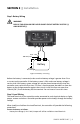
Section 3 | Installation - Battery over discharged (≤ 11.1V / 22.2V): Output to Load Terminals will be disconnected Protect the load as follows: - Overload or short circuit in the load connected to the Load Terminals: Output to Load Terminals will be disconnected Fuse - 10A Load(s) Figure 3-3 Load wiring Connect the Positive (+) and Negative (-) of load(s) to controller Load Terminals as shown in figure 3-3.
Section 3 | Installation The controller can accept 12V (36 cell) or 24V nominal (72 cell) PV panel(s) with maximum Open Circuit Voltage Voc of up to 50V. Solar Panel Positive Grounding Figure 3-4 Solar wiring Step 4: Confirm Wiring Double-check the wiring in step1 through 3 as shown in fig 3.5. Confirm correct polarity at each connection. Verify that all six terminals on the controller are tightened firmly. SAMLEX AMERICA INC.
Section 3 | Installation 3 2 Fuse 10A Fuse - 10A Battery 1 Figure 3.5 System wiring review Step 5: Install Fuse Install 10A fuse in each fuse holder in the following order: 1. 2. Battery circuit Load circuit Step 6: Confirm Power On When battery power is applied and the controller starts up, the Battery Status led “batt” (3, Fig 2.1) will be green. If the controller doesn't start up, or the Battery Status led error exists, please refer to Section 5 for Troubleshooting. 12 | SAMLEX AMERICA INC.
Section 4 | Operation PRINCIPLE OF OPERATION OF SOLAR CHARGING WITH SERIES TYPE PULSE WIDTH MODULATION (PWM) CONTROL The design and operation of MSK-10A is based on Series Type PWM (Pulse Width Modulation) control at PWM frequency of 25 Hz. PWM EXPLANATION The output of the PV Panel(s) is connected to the battery in series with a Mosfet Switch inside the controller.
Section 4 | Operation voltage is compensated by raising the average current by raising the Duty Cycle. These fast updates on battery voltage measurements and Duty Cycle corrections ensure charging of the battery at the specified Voltage Regulation Set Point with minimum voltage deviation. Optimum PWM Frequency: The PWM frequency can range from tens of Hz to around 1000 Hz. At higher frequencies, the time period between the cycles is lesser and is not sufficient to complete the electro-chemical reactions.
Section 4 | Operation Following two types charging cycles are used to ensure return of 100% capacity and also to prevent excessive gassing: - - Normal Charging Cycle (Fig 4.1A): This cycle is used for normal day-to-day charging. Charging is sequential: Stage 1: Bulk Stage (Maximum available Current = Instantaneous Short Circuit Current “Isc” of the panel) Stage 2: Absorption (Boost) Stage (Constant Voltage) Stage 3: Float Stage (Constant Voltage). Equalization Charging Cycle (Fig 4.
Section 4 | Operation This is a constant voltage stage and the Mosfet Switch operates under PWM control by feeding pulsing Short Circuit Current “Isc” with constantly reducing Duty Cycle (< 100% to > 0%) / average current to keep the battery voltage constant at the Absorption Transition Voltage Set Point “Va”. This is an intentional, controlled over voltage condition for the battery for 2 Hrs. This is necessary to return the balance 20% of the capacity.
Section 4 | Operation NOTE: During Float Stage, if the load current is more than the current from the PV Panel(s), the battery voltage will drop. If the battery voltage drops to 13.2V for 12V battery and 26.4V for 24V battery, the controller reverts to Stage 1: Bulk Stage. PWM DUTY Cycle is changed to 100% and STATUS LED “BATT” changes to steady Green thereafter.
Section 4 | Operation batteries. As the battery is discharged and charged, concentration of Sulphuric Acid becomes higher at the bottom of the cell and lower at the top of the cell. The low acid concentration reduces capacity at the top of the plates, and the high acid concentration accelerates corrosion at the bottom of the plates and shortens battery life.
Section 4 | Operation tive period of 2 Hours. If Equalization Transition Voltage Set Point “Ve” cannot be maintained continuously / cumulatively for 2 Hr, transition to Float Stage will NOT take place. STATUS LED “BATT” is steady Green during this stage NOTE: During Equalization Stage, if the load current is more than the current from the PV Panel(s), the battery voltage will drop. If the battery voltage drops to 13.2V for 12V battery and 26.
Section 4 | Operation LED Color & Pattern Status Green - Steady “Normal”: Battery is in Bulk Stage - Normal State of Charge of up to 80% Green - Slowly Flashing “Full”: Battery is in either Absorption (Boost) or Equalization or Float Stage and PWM regulated voltage charging is active. State of Charge is nearly full / completely full - 80% to 100% Orange - Steady “Under Voltage”: Battery Under Voltage Warning Signaling has been activated at ≤ 12V / ≤ 24V.
Section 4 | Operation i INFO Please note that in some applications like in Portable Solar Charging Kits, solar panel(s) will be permanently connected to the input terminals of the Charge Controller and the battery will be connected whenever the Portable Charging Kit is required to be used. In these applications, the modules will start generating power as soon as these are exposed to sunlight.
Section 5 | Protections, Troubleshooting & Maintenance PROTECTIONS PV Array Short Circuit If PV array short circuit occurs, clear it to resume normal operation. Overload in the Load(s) Connected to Load Terminals If the load current exceeds the maximum load current rating, the controller will disconnect the load. The greater the overload, the faster the load will be disconnected. A small overload could take a few minutes to disconnect.
Section 5 | Protections, Troubleshooting & Maintenance Symptom Possible Cause Remarks / Remedy Status LED “PV” (2) is Green - fast flashing and there is no output at the Load Terminals Battery Over Voltage Disconnect Protection has been activated due to high voltage of ≥ 16V / 32V at the battery output terminals. Solar Panel(s) and Load have been disconnected Disconnect the Solar panel(s) and discharge the battery Status LED “BATT” (3) is Orange - Steady.
Section 5 | Protections, Troubleshooting & Maintenance The following spurious LED indications may be seen at the Charge Controller and may be disregarded: Module(s) are exposed to Sunlight and Battery has not been connected • No LED indication Module(s) are exposed to Sunlight, Battery is Connected and then Removed.
Section 6 | Specifications Parameter Specification Charge Controller Type Series Type, PWM control PWM Frequency 25 Hz Battery System Voltage 12V / 24V Nominal; Auto Sensing (<18V sensed as 12V / >18V sensed as 24V) Rated Battery Current 10A Operating Voltage Range of Battery 6V to 36V Min. Battery Voltage to Start Controller 6V Charge Circuit Voltage Drop ≤ 0.26V Discharge Circuit Voltage Drop ≤ 0.
Section 6 | Specifications Sealed (Gel Cell) PARAMETER Bulk Charge Current Absorption (Boost) Voltage Absorption (Boost) Duration Float Voltage 12V 24V Sealed (AGM) 12V 24V Flooded 12V 24V Equal to Instantaneous Short Circuit Current Isc of the PV Panel(s) / Maximum 10A 14.2V 28.4V 2 Hrs 13.8V 14.4V 28.8V 2 Hrs 27.6V Equalization Voltage Not Equalized Equalization Duration Not Equalized 14.6V 29.2V 2 Hrs 13.8V 27.6V 13.8V 27.6V 14.6V 29.2V 14.8V 29.
SECTION 7 | Warranty 2 Year limited warranty MSK-10A Solar Charge Controller manufactured by Samlex America, Inc. (the “Warrantor“) are warranted to be free from defects in workmanship and materials under normal use and service. The warranty period is 2 years for the United States and Canada, and is in effect from the date of purchase by the user (the “Purchaser“). Warranty outside of the United States and Canada is limited to 6 months.
Contact Information Toll Free Numbers Ph: 800 561 5885 Fax: 888 814 5210 Local Numbers Ph: 604 525 3836 Fax: 604 525 5221 Website www.samlexamerica.com USA Shipping Warehouse Kent WA Canadian Shipping Warehouse Delta BC Email purchase orders to orders@samlexamerica.