DC-AC Power Inverter Pure Sine Wave PST-300-12 PST-300-24 Owner's Manual Please read this manual before installing your inverter
Owner's Manual | Index Section 1 Safety Instructions ................................................................. 3 Section 2 General Information .............................................................. 6 Section 3 Limiting Electromagnetic Interference (EMI) ........................ 11 Section 4 Powering Direct / Embedded Switch Mode Power Supplies (SMPS) ........................................................ 12 Section 5 Principle of Operation ..............................................
Section 1 | Safety Instructions The following safety symbols will be used in this manual to highlight safety and information: WARNING! Indicates possibility of physical harm to the user in case of non-compliance. ! CAUTION! Indicates possibility of damage to the equipment in case of non-compliance. i INFO Indicates useful supplemental information. Please read these instructions before installing or operating the unit to prevent personal injury or damage to the unit.
Section 1 | Safety Instructions Preventing fire and explosion hazards • Working with the unit may produce arcs or sparks. Thus, the unit should not be used in areas where there are flammable materials or gases requiring ignition protected equipment. These areas may include spaces containing gasoline-powered machinery, fuel tanks, and battery compartments. Precautions when working with batteries • Batteries contain very corrosive diluted sulphuric acid as electrolyte.
Section 1 | Safety Instructions the 12V battery version and 33.0 VDC for the 24V battery version to prevent permanent damage to the unit. Please observe the following precautions: • Ensure that the maximum charging voltage of the external battery charger / alternator / solar charge controller does not exceed 16.5 VDC for the 12V battery version and 33.0 VDC for the 24V battery version • Do not use unregulated solar panels to charge the battery connected to this unit.
SECTION 2 | General Information The following definitions are used in this manual for explaining various electrical concepts, specifications and operations: Peak Value: It is the maximum value of electrical parameter like voltage / current. RMS (Root Mean Square) Value: It is a statistical average value of a quantity that varies in value with respect to time. For example, a pure sine wave that alternates between peak values of Positive 169.68V and Negative 169.68V has an RMS value of 120 VAC.
SECTION 2 | General Information effect is a tendency to cancel each other. Hence, in a circuit containing both inductances and capacitances, the net Reactance (X) will be equal to the difference between the values of the inductive and capacitive reactances. The net Reactance (X) will be inductive if XL > XC and capacitive if XC > XL. Impedance, Z: It is the vectorial sum of Resistance and Reactance vectors in a circuit. Active Power (P), Watts: It is denoted as “P” and the unit is “Watt”.
SECTION 2 | General Information the inverter. The inverter can be sized based on the Active Power rating (Watts) without creating overload. Reactive Load: A device or appliance that consists of a combination of resistive, inductive and capacitive elements (like motor driven tools, refrigeration compressors, microwaves, computers, audio/ video etc.). These devices require Apparent Power (VA) from the inverter to operate. The Apparent Power is a vectorial sum of Active Power (Watts) and Reactive Power (VAR).
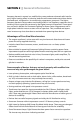
SECTION 2 | General Information frequency harmonic content in a modified sine wave produces enhanced radio interference, higher heating effect in inductive loads like microwaves and motor driven devices like hand tools, refrigeration / air-conditioning compressors, pumps etc. The higher frequency harmonics also produce overloading effect in low frequency capacitors due to lowering of their capacitive reactance by the higher harmonic frequencies.
SECTION 2 | General Information Power Rating of the Inverters The continuous output power rating of the inverter is specified in Active Power in Watts for resistive types of loads like heating elements, incandescent lamps etc. where Power Factor (PF) = 1. The Surge Power rating is for < 1 sec. Non resistive / reactive loads with Power Factor < 1 like motors (PF = 0.4 to 0.8), non Power Factor corrected electronics (PF = 0.5 to 0.6) etc, will draw higher Apparent Power in Volt Amps (VA).
SECTION 2 | General Information TABLE 2.1: INVERTER SIZING FACTOR Type of Device or Appliance Inverter Sizing Factor* Laser Printer / Other Devices using Quartz Lamps for heating 4 Switch Mode Power Supplies (SMPS): no Power Factor correction 3 Photographic Strobe / Flash Lights 4 (Note 1) * Multiply the Running Active Power Rating {Watts} of the appliance by this Factor to arrive at the Continuous Power Rating of the inverter for powering this appliance. TABLE 2.1: NOTES 1.
SECTION 4 | Powering Direct / Embedded Switch Mode Power Supplies (SMPS) Switch Mode Power Supplies (SMPS) are extensively used to convert the incoming AC power into various voltages like 3.3V, 5V, 12V, 24V etc. that are used to power various devices and circuits used in electronic equipment like battery chargers, computers, audio and video devices, radios etc. These power supplies use large capacitors in their input section for filtration.
SECTION 4 | Powering Direct / Embedded Switch Mode Power Supplies (SMPS) Input voltage RMS Current Inrush current Fig 4.1: Inrush current in an SMPS Peak Current Non-linear Input Current RMS Current Input Sine Wave Voltage TIME Fig. 4.2: High Crest Factor of current drawn by SMPS SAMLEX AMERICA INC.
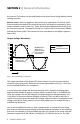
SECTION 5 | Principle of Operation These inverters convert DC battery voltage to AC voltage with an RMS (Root Mean Square) value of 120 VAC, 60 Hz RMS. The waveform of the AC voltage is a pure sine wave form that is same as the waveform of grid power (Supplementary information on pure sine waveform and its advantages are discussed on pages 8 & 9). Fig. 5.1 below specifies the characteristics of 120 VAC, 60 Hz pure sine waveform.
SECTION 6 | Layout 2 1 3 PST-300: Front 5 6 7 4 WARNING: REVERSE POLARITY WILL DAMAGE THE UNIT. AVERTISSEMENT : INVERSION DE POLARITÉ PEUT ENDOMMAGER L’UNITÉ. PST-300: Back LEGEND 1. 2. 3. 4. NEMA5-20R GFCI Duplex Receptacle Status LED - Power “ON” (GREEN) Status LED - Abnormal (ORANGE) ON/OFF Switch Cooling Fan Opening 5. 6. 7. Grounding Terminal Positive DC Input Terminal Negative DC Input Terminal PST-300-12-24 Layout Fig. 6.1: Layout of PST-300-12 and PST-300-24 SAMLEX AMERICA INC.
SECTION 7 | General Information on Batteries for Powering Inverters Lead-acid batteries can be categorized by the type of application: 1. Automotive service - Starting/Lighting/Ignition (SLI, a.k.a. cranking), and 2. Deep cycle service. Deep Cycle Lead Acid Batteries of appropriate capacity are recommended for the powering of inverters.
SECTION 7 | General Information on Batteries for Powering Inverters Typical Battery Sizes The Table 7.1 below shows details of some popular battery sizes: Table 7.1: Popular Battery Sizes BCI* Group Battery Voltage, V Battery Capacity, Ah 27 / 31 12 105 4D 12 160 8D 12 225 GC2** 6 220 * Battery Council International; ** Golf Cart Specifying Charging / Discharging Currents: C-Rate Electrical energy is stored in a cell / battery in the form of DC power.
SECTION 7 | General Information on Batteries for Powering Inverters Table 7.2 below gives some examples of C-Rate specifications and applications: Table 7.2: Discharge current rates - “C-Rates” Hours of discharge time “T” till the “End Point Voltage” C-Rate Discharge Current in Amps Fraction Decimal Subscript Example of C-Rate Discharge Currents for 100 Ah battery 0.5 Hrs. 2C 2C 2C 200A 1 Hrs. 1C 1C 1C 100A 5 Hrs. C/5 0.2C C5 20A 8 Hrs. (UPS application) C/8 0.125C C8 12.
SECTION 7 | General Information on Batteries for Powering Inverters 12 Volt Lead-Acid Battery Chart - 80˚F 16.5 C/5 C/10 16.0 CHARGE C/20 15.5 C/40 15.0 Battery Voltage in VDC 14.5 14.0 13.5 13.0 C/100 C/20 C/10 12.5 C/5 12.0 DISCHARGE C/3 11.5 11.0 10.5 Please note that X-axis shows % State of Charge. State of Discharge will be = 100% - % State of Charge. 10.0 9.5 9.0 0 10 20 30 40 50 60 70 80 90 100 110 120 130 Battery State of Charge in Percent (%) Fig. 7.
SECTION 7 | General Information on Batteries for Powering Inverters Table 7.3 (page 19) will show that a 100 Ah capacity battery will deliver 100% (i.e. full 100 Ah) capacity if it is slowly discharged over 20 hours at the rate of 5 Amperes (50W output for a 12V inverter and 100W output for a 24V inverter). However, if it is discharged at a rate of 50 Amperes (500W output for a 12V inverter and 1000W output for a 24V inverter) then theoretically, it should provide 100 AH ÷ 50 = 2 hours.
SECTION 7 | General Information on Batteries for Powering Inverters cables are thick enough to allow a negligible voltage drop between the battery and the inverter) . Inverters are provided with a buzzer alarm to warn that the loaded battery has been deeply discharged to around 80% of the rated capacity. Normally, the buzzer alarm is triggered when the voltage at the DC input terminals of the inverter has dropped to around 10.
SECTION 7 | General Information on Batteries for Powering Inverters In the example given above, the 10.5V Low Battery / DC Input Alarm would trigger at around 80% discharged state (20% SOC) when the C-Rate discharge current is C/5 Amps. However, for lower C-Rate discharge current of C/10 Amps and lower, the battery will be almost completely discharged when the alarm is sounded.
SECTION 7 | General Information on Batteries for Powering Inverters Please consider using the following Programmable Low Battery Cut-off / “Battery Guard” Models manufactured by Samlex America, Inc. www.samlexamerica.
SECTION 7 | General Information on Batteries for Powering Inverters terminal of Battery 3 is connected to the Positive terminal of Battery 2. The Negative terminal of Battery 2 is connected to the Positive terminal of Battery 1. The Negative terminal of Battery 1 becomes the Negative terminal of the 24V battery bank. Parallel Connection Cable “A” 12V Inverter or 12V Charger Battery 1 Battery 2 Battery 3 Battery 4 12V 12V 12V 12V Cable “B” Fig 7.
SECTION 7 | General Information on Batteries for Powering Inverters are connected in series to form a 12V, 200 Ah battery (String 1). Similarly, two 6V, 200 Ah batteries, Batteries 3 and 4 are connected in series to form a 12V, 200 Ah battery (String 2). These two 12V, 200 Ah Strings 1 and 2 are connected in parallel to form a 12V, 400 Ah bank. ! CAUTION! When 2 or more batteries / battery strings are connected in parallel and are then connected to an inverter or charger (See Figs 7.3 and 7.
SECTION 7 | General Information on Batteries for Powering Inverters The first step is to estimate the total AC watts (W) of load(s) and for how long the load(s) will operate in hours (H). The AC watts are normally indicated in the electrical nameplate for each appliance or equipment. In case AC watts (W) are not indicated, Formula 1 given above may be used to calculate the AC watts. The next step is to estimate the DC current in Amperes (A) from the AC watts as per Formula 2 above.
SECTION 8 | Installation WARNING! 1. Before commencing installation, please read the safety instructions explained in the Section titled “Safety Instructions” on page 3. 2. It is recommended that the installation should be undertaken by a qualified, licensed / certified electrician. 3. Various recommendations made in this manual on installation will be superseded by the National / Local Electrical Codes related to the location of the unit and the specific application.
SECTION 8 | Installation The corrosive fumes will corrode and damage the unit and if the gases are not ventilated and allowed to collect, they could ignite and cause an explosion. Accessibility: Do not block access to the front panel. Also, allow enough room to access the AC receptacles and DC wiring terminals and connections, as they will need to be checked and tightened periodically. Preventing Radio Frequency Interference (RFI): The unit uses high power switching circuits that generate RFI.
SECTION 8 | Installation Mounting Orientation The unit has air intake and exhaust openings for the cooling fan(s). It has to be mounted in such a manner so that small objects should not be able to fall easily into the unit from these openings and cause electrical / mechanical damage.
SECTION 8 | Installation tion of the diversion load may damage the battery as well as the inverter or other DC loads connected to the battery due to high voltages generated during conditions of high winds (for wind generators), high water flow rates (for hydro generators). It is, therefore, to be ensured that the diversion load is sized correctly to prevent the above over voltage conditions.
SECTION 8 | Installation up to AWG #1. Wires thicker than AWG #1 are designated AWG 1/0, AWG 2/0, AWG 3/0 and so on. In this case, increasing AWG # denotes thicker wire. The DC input circuit is required to handle very large DC currents and hence, the size of the wires and connectors should be selected to ensure minimum voltage drop between the battery and the inverter.
SECTION 8 | Installation WARNING! Use of an appropriately sized external fuse as described above is mandatory to provide safety against fire hazard due to accidental short circuit in the battery wires. Please note that the DC side fuse(s) inside the unit are designed to provide protection to the internal components of the inverter. These fuses will NOT blow if there is a short circuit along the length of wires connecting the battery and the inverter.
SECTION 8 | Installation • Wire set with battery clamp - For PST-300-12: AWG#12 - For PST-300-24: AWG#14 WARNING Limiting Power Draw from 12V Power Outlet in Vehicles: - 12V power outlet in a vehicle is normally fused at around 15A. This limits the power draw from this outlet to around 150W. - When powering PST-300 (rated at 300W) from the 12V power outlet in a vehicle, please ensure the AC load is limited to < 150W. Power draw > 150W will blow the 15A fuse in the vehicle.
SECTION 8 | Installation or electrocuted. A Ground Fault Circuit Interrupter (GFCI) protects people from electric shock by detecting leakage and cutting off the AC source. The AC output of this inverter is available through a NEMA5-20R GFCI Duplex Receptacle. The Neutral slot of this receptacle (longer rectangular slot) is internally bonded to the metal chassis of the inverter. There is a Green indicator light that will be lighted when the GFCI is operating normally.
SECTION 8 | Installation be connected to the Hot and Neutral of the Sub-Panel. As the Neutral is not bonded to Earth Ground in the Sub-Panel, the GFCI in the inverter will not trip. Grounding to Earth or to other designated ground For safety, ground the metal chassis of the inverter to the Earth Ground or to the other designated ground (For example, in a mobile RV, the metal frame of the RV is normally designated as the negative DC ground).
SECTION 9 | Operation ! CAUTION! Please note that the On/Off switch is not switching the high power battery input circuit. Parts of the DC side circuit will still be alive even when the switch is in the off position. Hence, disconnect the DC and AC sides before working on any circuits connected to the inverter. When the inverter is switched on, the Status LED (2, Fig. 6.1) will turn Green. This LED indicates that the inverter is operating normally.
SECTION 10 | Protections The inverter has been provided with protections detailed below: Overload / Short Circuit Shut Down The inverter can provide a higher than normal instantaneous power (< 1 second) limited to the surge power rating of the inverter. Also, the inverter can provide continuous power limited to the continuous power rating of the inverter. If there is an overload beyond these specified limits, the AC output of the unit will be shut down permanently.
SECTION 10 | Protections will increase. The temperature of a critical hot spot inside the inverter is monitored and at 95° C, the AC output of the inverter is shut down temporarily. The Status LED (2) will turn ORANGE and a buzzer is sounded. The GREEN indication light on the GFCI will be OFF. The unit will automatically reset after the hot spot has cooled down to 70°C.
SECTION 11 | Trouble Shooting Guide ISSUE POSSIBLE CAUSE When switched ON, Status LED (2) does not light. Buzzer is off. There is no AC output voltage. GREEN indication light on the GFCI is OFF. There is no voltage at the DC input terminals / 12V power outlet in the vehicle REMEDY Check the continuity of the battery input circuit. Check that the internal/external battery fuse/ vehicle fuse for 12V power outlet is intact. Replace if blown.
SECTION 11 | Trouble Shooting Guide ISSUE There is no AC output. Status LED (2) is ORANGE. Buzzer is on. GREEN indication light on the GFCI is OFF. POSSIBLE CAUSE Shut-down due to high input DC voltage – > 16.5V for 12V versions and > 33V for 24V versions. REMEDY Check that the voltage at the DC input terminals is less than 16.5V for 12V versions and less than 33V for 24V versions. Ensure that the maximum charging voltage of the battery charger / alternator / solar charge controller is below 16.
SECTION 12 | Specifications Model No. PST-300-12 PST-300-24 120 VAC ± 3% 2.54A 60 Hz ± 1% Pure Sine Wave 120 VAC ± 3% 2.
SECTION 12 | Specifications battery vehicle outlet and 20 Amperes from 24V battery vehicle outlet. Ensure that the electrical system in your vehicle can supply this product without causing the vehicle fusing to open. This can be determined by making sure that the fuse in the vehicle, which protects the outlet, is rated higher 40 amperes (12V battery), or 20 amperes (24V battery). Information on the vehicle fuse ratings is typically found in the vehicle operator's manual.
SECTION 13 | Warranty 2 Year limited warranty The PST-300-12 and PST-300-24 are manufactured by Samlex America, Inc. (the “Warrantor“) is warranted to be free from defects in workmanship and materials under normal use and service. The warranty period is 2 years for the United States and Canada, and is in effect from the date of purchase by the user (the “Purchaser“). Warranty outside of the United States and Canada is limited to 6 months.
Contact Information Toll Free Numbers Ph: 800 561 5885 Fax: 888 814 5210 Local Numbers Ph: 604 525 3836 Fax: 604 525 5221 Website www.samlexamerica.com USA Shipping Warehouse Kent WA Canadian Shipping Warehouse Delta BC Email purchase orders to orders@samlexamerica.