Pure Sine Wave Power Inverter SSW-350-12A SSW-600-12A SSW-1000-12A SSW-1500-12A SSW-2000-12A Owner's Manual Please read this manual before installing your inverter
Owner's Manual | Index Section 1 Important Safety Instructions ................................................ 3 Section 2 Design Features and Principle of Operation .......................... 5 Section 3 Layout and Dimensions ......................................................... 7 Section 4 Installation ......................................................................... 10 Section 5 Operation .........................................................................
Section 1 | Important Safety Instructions 1.1 THIS MANUAL CONTAINS IMPORTANT INFORMATION REGARDING SAFETY, OPERATION, MAINTENANCE AND STORAGE OF THIS PRODUCT. BEFORE USE, READ AND UNDERSTAND ALL CAUTIONS, WARNINGS, INSTRUCTIONS AND PRODUCT LABELS, PLUS YOUR VEHICLE’S BATTERY MANUFACTURER GUIDELINES. FAILURE TO DO SO COULD RESULT IN INJURY AND/OR PROPERTY DAMAGE. 1.2 T o ensure reliable service, your power inverter must be installed and used properly.
Section 1 | Important Safety Instructions 7. This is not a toy - keep away from children. 8. Do not insert any object into the ventilation slots or the fan opening(s). 1.4 ! CAUTION! 1. The metal chassis and the input Negative terminal of the inverter are internally connected to the Ground terminals of the AC outlets. Hence, the input Negative terminal should be used as the grounding terminal.
Section 1 | Important Safety Instructions the value of the current carried through it. The resistance of the wire is inversely proportional to the cross-sectional area of the wire (designated in mm2 or AWG) and directly proportional to its length i.e. thinner and longer wire has higher resistance and hence, produces higher voltage drop. Similarly, thicker and shorter wire has lower resistance and hence, produces lower voltage drop.
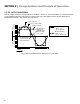
Section 2 | Design Features and Principle of Operation 2.5 THE OUTPUT WAVEFORM VOLTS − VOLTS + The AC output waveform of the SSW-series inverter is known as “Pure Sine Wave” or “True Sine Wave”. It is a waveform that has characteristics same as the sine wave shape of utility power (See Fig 2.1). Modified Sine Wave is also shown for comparison. 180 160 140 120 100 80 60 40 20 0 20 40 60 80 100 120 140 160 180 Vpeak = 162.
Section 3 | Layout and Dimensions 3.1 LAYOUT 3.1.1 SSW-350-12A, SSW-600-12A 10(a) 1 6 1 5 9(b) 2 8 3 4 11 Fig 3.1.1 Front of the unit 9 9(b) 9(a) 7 10(b) Fig 3.1.2 Back of the unit Legend for Fig 3.1.1 and 3.1.2 AC Outlets: 2 x NEMA5-15R 1. 2. ON/OFF Switch USB Charging Port= + 5V, 500mA 3. 4.
Section 3 | Layout and Dimensions 3.1.2 SSW-1000-12A, SSW-1500-12A and SSW-2000-12A 1(a) 1(b) 3 9(b) 2 4 6 9(a) 5 Fig 3.2.1 Front of the unit 11 9 10 9(a) 8 7 Fig 3.2.2 Back of the unit Legend for Fig 3.2.1 and 3.2.2 1(a). AC Outlets: NEMA5-20R Duplex GFCI receptacles 1(b). Green indicator light on the GFCI receptacles. Will be ON when normal. Will be OFF when tripped 2. ON/OFF Switch 8P8C Modular Jack (Also called RJ-45 Jack) for connecting Remote Control Model SSW-R1-12B 3. 4.
Section 3 | Layout and Dimensions 3.2 DIMENSIONS 255 225 SSW-350-12A SSW-600-12A HEIGHT: 59 OVERALL (W x D x H): 155 x 225 x 59 HEIGHT: 59 OVERALL (W x D x H): 155 x 255 x 59 155 150 • NOT TO SCALE • DIMENSIONS ARE IN MM 155 • NOT TO SCALE • DIMENSIONS ARE IN MM 6.6 6.6 6.5 6.5 98 Fig. 3.3 Dimensions: SSW-350-12A 129 Fig. 4 Dimensions: SSW-600-12A 6.6 6.
Section 4 | Installation WARNING! 1. Before commencing installation, please read the safety instructions explained in Section 1 titled “Important Safety Instructions”. 2. It is recommended that the installation should be undertaken by a qualified, licensed / certified electrician. 3. Various recommendations made in this manual on installation will be superseded by the National / Local Electrical Codes related to the location of the unit and the specific application. 4.
Section 4 | Installation 4.2 MOUNTING Please refer to Figs 3.3 to 3.6 for dimensions and mounting details. The inverter has four mounting slots that allow the unit to be fastened against a bulkhead, floor, wall or other flat surface. Ideally, the mounting surface should be cool to the touch. It is more electrically efficient to use longer AC wiring than DC wiring, so install the inverter as close as possible to the 12 VDC power source.
Section 4 | Installation For normal operation of the inverter, the DC power source must provide >11.0 ± 0.3V and < 15.3 ± 0.3V and the required current. This DC power source must be a well-regulated DC power supply or alternator and deep cycle battery system typically found in vehicles and marine crafts. The DC power source may also be two or more 12 volt batteries connected in parallel. On larger applications, the power source may be several batteries connected in parallel as shown in Fig 4.2.
Section 4 | Installation Table 4.1 provides details of Battery Cables and DC Fuses for connecting the battery to the DC input terminals of the inverter (7, 8 in Figs 3.1.2 and 3.2.2) Table 4.1 Sizing of Cables and Fuses for DC Input Model No. Rated DC Input Current NEC Ampacity (2) (3) (4) SSW-350-12A 35A 43.75A 50A SSW-600-12A 60A 75A 80A SSW-1000-12A 100A 125A 150A SSW-1500-12A 150A 187.5A 200A SSW-2000-12A 200A 250A 300A (1) Ampere Rating of the Fuse (Note 1) Part. No.
Section 4 | Installation 4.7). For this, cut the cable around 2” from the lug and splice it to the appropriate cable to be used for permanent installation (Cable sizing as per Table 4.1). Use appropriate Butt Splice Connector. SSW-1000-12A, SSW-1500-12A and SSW-2000-12A The inverter side of the DC input cable has to be terminated with a Ring / Tongue type of terminal lug to fit M9 or 3/8” size of stud on the DC Input terminal (7, 8 in Fig 3.2.2). The terminal lug may be crimped / soldered. 4.
Section 4 | Installation 4.9 REMOTE CONTROL Remote Control Model No. SSW-R1-12B has been provided only for Model SSW-1000-12A, SSW-1500-12A and SSW-2000-12A. Please refer to separate manual for the above remote. ! CAUTION! When wiring Remote Control SSW-R1-12B, the ON/OFF Switch on the inverter (2, Fig 3.1.1 and 3.2.1) should be in OFF position.
Section 5 | Operation WARNING! Do not connect directly to AC distribution wiring. This inverter is NOT grid interactive. 5.3 OPERATING ENVIRONMENT For best operating results, the inverter should be placed on flat surface, such as the ground, car floor, or other solid surface. The inverter should only be used in locations that meet the following criteria: DRY Do not allow water and/or other liquids to come into contact with the power inverter.
Section 5 | Operation Table 5.1 lists some common loads that require high surge power on start up. A “Sizing Factor” has been recommended against each which is a Multiplication Factor to be applied to the rated running Watt rating of the load to arrive at the continuous power rating of the inverter (Multiply the running Watts of the device / appliance by the Sizing Factor). Table 5.
Section 5 | Operation To get an estimate of the current (in Amps) that the battery is delivering to power a particular AC side load, divide the load's AC consumption power (in Watts) by (10). Keep in mind that most appliances are not operating for long periods of time. For example, a typical home-use coffee maker draws 500 Watts during its brew time of 5 minutes, but it maintains the temperature of the pot at about 100 Watts. Typical use of a microwave is only for a few minutes, sometimes at low power.
Section 6 | Protections 6.4 OVERLOAD PROTECTION The inverter will automatically shut down when the continuous draw exceeds rated Watts. It will be latched in shut down condition and will require manual reset by switching OFF the ON/OFF Switch (2, Figs 3.1.1 and 3.2.1), waiting for 3 minutes and switching ON again (internal latching circuit does not de-energize immediately after Switching OFF). SSW-1000/1500/2000 cannot be reset by using the ON/OFF Push Button on the Remote Control SSW-R1-12B.
Section 7 | Troubleshooting Guide TROUBLE / SYMPTOMS No AC output POSSIBLE CAUSE(S) SUGGESTED REMEDIES Over Temperature Shutdown In case the fan fails or if the cooling is inadequate due to higher ambient temperature or restricted airflow, the temperature inside the inverter will start rising. Temperature rise is sensed at one of the DC side Mosfets. If this temperature exceeds 90C to 100C, the AC output will be switched off. 1.
Section 7 | Troubleshooting Guide TROUBLE / SYMPTOMS POSSIBLE CAUSE(S) AC output is available Intermittent buzzer alarm due to intermittent high AC loads On the Inverter • Green LED on the front panel of the inverter is ON • Red LED is OFF • Buzzer alarm sounds intermittently when DC input voltage drops to Low DC Input Voltage Alarm Threshold of 11V +/- 0.3V when delivering high power loads • Yellow LED comes ON when buzzer alarm is sounded. 1.
Section 7 | Troubleshooting Guide TROUBLE / SYMPTOMS No AC output POSSIBLE CAUSE(S) SUGGESTED REMEDIES Shutdown due to high DC input voltage DC input voltage has risen to High DC Input Voltage Shutdown Threshold of 15.3V +/- 0.3V 1. Switch OFF the AC load and the inverter. 2. Disconnect the DC input to the inverter 3. Check the output voltages of the battery and charging source and ensure these are below the High DC Input Voltage Shutdown Threshold of 15.3V +/- 0.3V 4.
Section 9 | SPECIFICATIONS Model No. SSW-350-12A SSW-600-12A SSW-1000-12A SSW-1500-12A SSW-2000-12A DC INPUT VOLTAGE RANGE INPUT 10.5 - 15.3 VDC (± 0.3 VDC) DC INPUT CURRENT at rated LOAD 35A 60A 100A 150A 200A DC INPUT CURRENT AT NO LOAD < 0.5A < 0.7A < 0.9A < 1.0A < 1.
Section 10 | WARRANTY 2 Year limited warranty SSW-350-12A, SSW-600-12A, SSW-1000-12A, SSW-1500-12A AND SSW-2000-12A are manufactured by Samlex America, Inc. (the “Warrantor“) are warranted to be free from defects in workmanship and materials under normal use and service. The warranty period is 2 years for the United States and Canada, and is in effect from the date of purchase by the user (the “Purchaser“). Warranty outside of the United States and Canada is limited to 6 months.
NOTES:
Contact Information Toll Free Numbers Ph: 1 800 561 5885 Fax: 1 888 814 5210 Local Numbers Ph: 604 525 3836 Fax: 604 525 5221 Website www.samlexamerica.com USA Shipping Warehouses Kent, WA Plymouth, MI Canadian Shipping Warehouse Delta BC Email purchase orders to orders@samlexamerica.
Convertisseur de courant continu alternatif à onde sinusoïdale pure SSW-350-12A SSW-600-12A SSW-1000-12A SSW-1500-12A SSW-2000-12A Manuel du propriétaire Veuillez lire ce manuel avant de faire fonctionner votre convertisseur
Owner's Manual | Index Section 1 Instructions importantes concernant la sécurité .....................3 Section 2 Les caractéristiques de conception et principe de fonctionnement .................................................. 5 Section 3 Disposition et dimensions ..................................................... 7 Section 4 Installation ......................................................................... 10 Section 5 Fonctionnement ...........................................................
Section 1 | Instructions importantes concernant la sécurité 1.1 C E MANUEL CONTIENT DES INFORMATIONS IMPORTANTES CONCERNANT LA SÉCURITÉ, LE FONCTIONNEMENT, L’ENTRETIEN ET L’ENTREPOSAGE DE CE PRODUIT. AVANT DE L’UTILISER, LISEZ ET ASSUREZ-VOUS DE BIEN COMPRENDRE TOUS LES AVERTISSEMENTS ET LES MISES EN GARDE, LES INSTRUCTIONS ET LES ÉTIQUETTES DU PRODUIT AINSI QUE LES DIRECTIVES DU FABRICANT DE LA BATTERIE DE VOTRE VÉHICULE. NE PAS S’Y CONFORMER POURRAIT ENTRAÎNER DES BLESSURES OU DES DOMMAGES MATÉRIELS. 1.
Section 1 | Instructions importantes concernant la sécurité 7. Ce n'est pas un jouet - Tenir hors de portée des enfants. 8. N'insérez aucun objet dans les orifices de ventilation ou dans l'ouverture du ventilateur(s). 1.4 ! ATTENTION! 1. Le châssis métallique et la borne négative d'entrée de l'inverseur sont connectés en interne à la masse les bornes de l'AC outlets. Par conséquent, la prise négative du terminal devrait être utilisée comme borne de terre.
Section 1 | Instructions importantes concernant la sécurité 1.5 INFORMATIONS IMPORTANTES CONCERNANT LE CÂBLAGE Des convertisseurs installés avec câblage de calibre inapproprié par rapport à la longueur et à la quantité de courant devant être acheminé entraînent une perte de puissance importante et un temps réduit de fonctionnement de la batterie. Le courant circulant le long d’un câble produit une chute de voltage due à la résistance du câble et à la quantité de courant transporté.
Section 2 | L es caractéristiques de conception et principe de fonctionnement 2.5 LA FORME D’ONDE DE SORTIE VOLTS − VOLTS + La forme d'onde de sortie CA des séries de convertisseurs SSW est connue sous le nom d'«onde sinusoïdale pure» ou «onde sinusoïdale véritable». C’est une forme d’onde ayant les mêmes caractéristiques que la forme d’onde sinusoïdale du réseau de distribution public d’électricité. (Voir Fig. 2.1). Onde sinusoïdale modifiée est également présenté à titre de comparaison.
Section 3 | Disposition et dimensions 3.1 Mise en page 3.1.1 SSW-350-12A, SSW-600-12A 10(a) 1 6 1 5 9(b) 2 8 3 4 11 Fig. 3.1.1 Avant de l'unité 9 9(b) 9(a) 7 10(b) Fig 3.1.2 Arrière de l'unité Légende Figure 3.1.1 et 3.1.2 1. AC : 2 x sorties NEMA5-15R 2. Interrupteur MARCHE/ARRÊT 3. La charge USB Port = + 5V, 500mA 4. Voyant jaune : est allumé au cours (i) shutdown en cas de surchauffe (ii) alarme due à faible tension en entrée CC (iii) fermées en raison de la tension d'entrée c.c.
Section 3 | Disposition et dimensions 3.1.2 SSW-1000-12A, SSW-1500-12A and SSW-2000-12A 1(a) 3 1(b) 9(b) 2 4 6 9(a) 5 Fig. 3.2.1 Avant de l'unité 11 9 10 9(a) 8 7 Fig 3.2.2 Arrière de l'unité Légende Figure 3.2.1 et 3.2.2 1(a). Points de vente : NEMA5-20AC R récipients GFCI Duplex 1(b). Voyant vert sur le FGIC récipients. Seront sur lorsque normal. S'éteint lorsqu'il est déclenché 2. Interrupteur MARCHE/ARRÊT 3.
Section 3 | Disposition et dimensions 3.2 DIMENSIONS 255 225 SSW-350-12A SSW-600-12A HAUTEUR : 59 DANS L'ENSEMBLE (L X P X H) : 155 x 225 x 59 HAUTEUR : 59 DANS L'ENSEMBLE (L X P X H) : 155 x 255 x 59 155 150 • N'EST PAS À L'ÉCHELLE • LES DIMENSIONS SONT EN MM 6,5 98 Fig. 3.3 Dimensions: SSW-350-12A 129 Fig.
Section 4 | Installation MISE EN GARDE! 1. Avant de faire l’installation, veuillez lire les «Consignes de Sécurité». 2. On recommande que l'installation soit faite par un(e) électricien(ne) CERTIFIÉ(E). 3. Il y a plusieurs consignes trouvées dans ce guide qui ne sont pas toujours appliquables si une norme nationale ou locale en prend place, concernant par example l'endroit d'installation ou à l'usage de l'appareil. Quelques exemples sont écrites ci-dessous. 4.
Section 4 | Installation 4.2 Montage Veuillez vous reporter aux figues 3.3 à 3.6 pour les dimensions et détails de montage. Le convertisseur dispose de quatre emplacements de fixation qui permettent à l'unité d'être fixée contre une cloison, étage, mur ou toute autre surface plane. Idéalement, la surface de montage doivent être froids au toucher. Le convertisseur peut fonctionner dans toutes les positions, cependant, s’il est monté sur un mur, fixez-le horizontalement (Fig.
Section 4 | Installation Pour le fonctionnement normal du convertisseur, la source d’alimentation CC doit fournir >11.0 ± 0.3V et < 15.3 ± 0.3V et la quantité nécessaire de courant. Cette source d’alimentation doit être une source de courant CC régulière ou un alternateur et une batterie à décharge complète telle que l’on trouve dans les véhicules et les embarcations. La source d’alimentation CC peut également consister de deux batteries de 12 volts ou plus montées en parallèle.
Section 4 | Installation Le tableau 4.1 fournit des détails sur les câbles de batterie et DC fusibles pour connexion de la batterie à la bornes d'entrée CC du convertisseur (7, 8 dans les figues 3.1.2 et 3.2.2) Tableau 4.1 Le dimensionnement des câbles et des fusibles pour l'entrée CC Modèle No. (1) SSW-350-12A SSW-600-12A Courant d'entrée CC nominale NEC Courant admissible Ampérage du fusible (Note 1) (2) (3) (4) 35A 60A 43.75A 75A 50A 80A La partie.
Section 4 | Installation SSW-600-12A: le côté de l'onduleur du câble d'entrée CC doit être résilié avec un personnalisé, Cosse rectangulaire plat (10b, Fig 3.1.2). La cosse s'insère dans la fente rectangulaire dans la borne d'entrée CC (7, 8 fig 3.1.2) et n'est pas serré à l'aide de vis M4. Pour une installation permanente, utilisez la borne ergots (10b, Fig 3.1.2) qui viennent avec le jeu de câbles fourni avec le boîtier (voir section 4.4).
Section 4 | Installation ! A TTENTION! Connecteurs desserrés peuvent causer la surchauffe de câbles et isolation fondue. 4.9 Contrôle à distance Modèle de contrôle à distance n° SSW-R1-12B a été fournie uniquement pour le modèle SSW-1000-12A, SSW-150012A et SSW-2000-12A. Veuillez vous reporter au manuel séparé pour le ci-dessus remote. ! A TTENTION! Lors du câblage de Télécommande SSW-R1-12B, l'interrupteur de MARCHE/ARRÊT de l'onduleur (2, Fig 3.1.1 et 3.2.1) doit être en position ARRÊT.
Section 5 | Fonctionnement Le convertisseur est conçu pour être connecté directement à des équipements électriques et électroniques de la façon décrite ci-dessus. Ne pas connecter le convertisseur de courant à un réseau de câblage CA domestique ou de véhicule de camping. Ne pas connecter le convertisseur de courant à aucun circuit de charge CA dans lequel le conducteur neutre est mis à la terre ou au pôle négatif de la source CC (batterie).
Section 5 | Fonctionnement La surtension requise pour certains types spécifiques d’appareils doit être vérifiée auprès du fabricant, testée réellement ou au mieux, devinée. Tableau 5.1 donne une liste de charges courantes nécessitant une surtension de démarrage élevée.
Section 5 | Fonctionnement 4. Ajoutez la consommation de watt/heures pour chaque appareil pour obtenir le total watt/heures de consommation pour tous les appareils devant être utilisés. 5. Divisez le total de consommation watt/heures sur le côté CA par 10 pour obtenir le total d’ampères/heures de consommation sur le côté 12 VCC pour faire fonctionner les appareils. 6.
Section 6 | Protections 6.3 PROTECTION CONTRE LA SURTENSION DE VOLTAGE Le convertisseur se fermera automatiquement lorsque le voltage d’entrée dépasse 15,3V ± 0,3V. L'unité se réinitialise automatiquement lorsque la tension chute à 14,9 ± 0.2V. Un voltage d’entrée dépassant 16V pourrait endommager le convertisseur. Se reporter à la Section 7 - Guide de dépannage pour plus d'informations sur les symptômes, causes et remèdes liés à cette protection. 6.
Section 7 | Guide de dépannage SYMPTÔME Aucune sortie CA Sur l’onduleur • DEL verte du panneau frontal est ALLUMEE • DEL jaune sur panneau frontal de l’onduleur pour « Erreur d’entrée » est ALLUMEE • DEL rouge est ETEINTE • Aucune alarme sonore Sur télécommande SSW-R1-12B (Pour SSW-1000-1500-2000-12A) • Tension d’entrée de CC est affichée • Barre-graphe de puissance est ETEINT • Message “Erreur d’entrée” clignote Aucune sortie CA Sur l’onduleur • DEL verte, DEL jaune et DEL rouge du panneau frontal so
Section 7 | Guide de dépannage SYMPTÔME Aucune sortie CA (Pour SSW-1000-1500-2000-12A) Sur le GFCI Duplex de NEMA5-20R outlet • Petite DEL verte du disjoncteur de fuite à la terre est ETEINTE • Le “Bouton de réinitialisation » s’affiche Sur l’onduleur • DEL verte du panneau frontal est ALLUMEE • DEL jaune et rouge du panneau frontal de l’onduleur sont ETEINTES • Aucune alarme sonore CAUSE PROBABLE SOLUTION SUGGÉRÉE GFCI s’est déclenché en raison d’un défaut a la terre / fuite du côté charge 1.
Section 7 | Guide de dépannage SYMPTÔME Aucune sortie CA Sur l’onduleur • DEL verte du panneau frontal • De l’onduleur est ALLUMEE • DEL rouge est ETEINTE • Alarme sonore constante • DEL jaune est ALLUMEE Sur télécommande SSW-R1-12B (Pour SSW-1000-1500-2000-12A) • La tension d’entrée de CC s’affiche, chute et atteint un seuil d’alarme de 10.5V +/- 0.
Section 7 | Guide de dépannage SYMPTÔME CAUSE PROBABLE SOLUTION SUGGÉRÉE L’onduleur de s’arrête pas lorsque la télécommande SSW-R112B est ETEINTE. (Pour SSW-1000-1500-2000-12A) L’interrupteur ON/OFF de l’onduleur est ALLUME Lorsque vous utilisez la télécommande SSW-R1-12B, assurez-vous que l’interrupteur ON /OFF de l’onduleur est ETEINT. Appareil électrique motorisé ne démarre pas Un courant excessif de démarrage depuis la charge, active le démarrage graduel du circuit et réduit la tension de sortie.
Section 9 | Caractéristiques N° de modèle SSW-350-12A SSW-600-12A SSW-1000-12A SSW-1500-12A SSW-2000-12A 10,5 - 15,3 VCC (±0,3 VCC) PLAGE DE TENSION CC D’ENTRÉE ENTRÉE ENTRÉE DE COUFANT CC à la CHARGE NONminale ENTRÉE DE COURANT CC SANS CHARGE 35A 60A 100A 150A 200A < 0,5A < 0,7A < 0,9A < 1,0A < 1,1A FRÉQUENCE DE SORTIE CA 115 VAC (± 5 VAC) 60 Hz (± 1Hz) FORME D’ONDE DE SORTIE AC PURE SINE WAVE TENSION DE SORTIE CA SORTIE PORTS PROTECTIONS PUISSANCE DE SORTIE CONTINUE ACTIVE 350W 60
Section 10 | Garantie GARANTIE LIMITEE SOUS 2 ANS SSW-350-12A, SSW-600-12A, SSW-1000-12A, SSW-1500-12A, SSW-2000-12A, fabriqués par Samlex America, Inc. (le « Garant ») sont garantis être non défectueux dans la conception et dans les matériaux, moyennant une utilisation et un service normaux. La période de garantie est de 2 ans pour les Etats-Unis et le Canada, et prend effet le jour de l’achat par l’utilisateur (« l’Acheteur »). La garantie hors des Etats Unis et du Canada est limitée à 6 mois.
Information Contact Numéros gratuits Tel : 1 800 561 5885 Fax : 1 888 814 5210 Numéros locaux Tel : 604 525 3836 Fax : 604 525 5221 Site internet www.samlexamerica.com Entrepôts USA Kent, WA Plymouth, MI Entrepôt Canada Delta, BC Adresse email pour passer commande orders@samlexamerica.