
User Manual

13
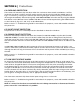
SECTION 4 | Installation
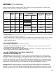
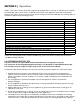
Table 4.1 provides details of Battery Cables and DC Fuses for connecting the battery to the DC input
terminals of the inverter (7, 8 in Figs 3.1.2 and 3.2.2)
Table 4.1 Sizing of Cables and Fuses for DC Input
Model No.
(1)
Rated
DC Input
C
urrent
(2)
NEC
Ampacity
(3)
Ampere
Rating of
the Fuse
(Note 1)
(4)
Part. No. of MRBF Fuse /
Fuse Assembly
Cable Size for
up to 4 ft from
Battery to Inverter
(Note 2)
(7)
Cable Size for
up to 6 ft from
Battery to Inverter
(Note 2)
(8)
By Blue Sea
Systems
(5)
By Samlex
America
(6)
SSW-350-12A 35A 43.75A 50A
F
use Block: 5191
- AWG#8 AWG#6
F
use: 5177
SSW-600-12A 60A 75A 80A
F
use Block: 5191
- AWG#6 AWG#4
F
use: 5181
SSW-1000-12A 100A 125A 150A
F
use Block: 5191
- AWG#4 AWG#2
F
use: 5185
SSW-1500-12A 150A 187.5A 200A - DC-F
A-200 A
WG#2 AWG#1/0
SSW-2000-12A 200A 250A 300A - DC-F
A-300
A
WG#2/0 or
2X AWG#2
AWG#2/0 or
2XAWG#2
Notes for Table 4.1
1. Ampere ratings of the fuse (Column 4) is based on the NEC Ampacity (Column 3) = 1.25 times the rated
DC input current of the inverter (Column 2).
2. Cable sizing (Columns 7 and 8) is based on: (i) the Ampere rating of the fuse (Column 4) or 2% voltage
drop, whichever is thicker (ii) Ambient temperature of 30°C (iii) Wire insulation rated at 105°C (iv)
Cables routed in free air.
4.5 DC INPUT TERMINALS
The following DC input terminals have been provided:
a) SSW-350-12A and SSW-600-12A: Thumb screw – size M4 (7,8 in Fig 3.1.2). Accepts customized Flat
Rectangular Terminal Lugs (10b, Fig 3.1.2)
b) SSW-1000-12A, SSW-1500-12A and SSW-2000-12A: Stud and nut – size M9 (7, 8 in Fig 3.2.2). Accepts
Ring / Tongue Terminal Lugs for M9 or 3/8” stud size
4.6 CABLE TERMINATION FOR DC INPUT CONNECTORS
SSW-350-12A and SSW-600-12A
SSW-350-12A: The inverter side of the DC input cable has to be terminated with a customized, Flat
Rectangular Terminal Lug (10b, Fig 3.1.2). The terminal lug ts in the rectangular slot in the DC input
terminal (7, 8 in Fig 3.1.2) and is tightened using M4 Thumb Screw. For permanent installation, use the
terminal lugs (10b in Fig 3.1.2) that come with the Cable Set provided with the unit (Please see Section
4.7). For this, cut the cable around 2” from the lug and splice it to the appropriate cable to be used for
permanent installation (Cable sizing as per Table 4.1). Use appropriate Butt Splice Connector.
SSW-600-12A: The inverter side of the DC input cable has to be terminated with a customized, Flat
Rectangular Terminal Lug (10b, Fig 3.1.2). The terminal lug ts in the rectangular slot in the DC input
terminal (7, 8 in Fig 3.1.2) and is tightened using M4 Thumb Screw. For permanent installation, use the
terminal lugs (10b in Fig 3.1.2) that come with the Cable Set provided with the unit (Please see Section