
Specifications

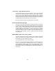
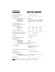
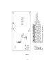

Figure 1 - Layout of Power Supply Module
S1 to S4 Holes for 4 screws to fasten the module to the chassis
S5 & S6 Holes for 2 screw to connect to the Positive and Negative output BUS Bars
L & N L ( line ) and N ( neutral ) terminals for 120V, 60 Hz input power supply wires
LED 1 Terminal for “ON“ status for opto-isolated remote indication
LED 2 Terminal for “LED“ PSM status for front panel indication
JUMP 1 Jumper terminal for connecting share BUS wire
F1 Fuse
VR1 Potentiometer for output voltage adjustment
17.
Figure 1.