DR-S0426 / DRE-S0426P 4 Channel Stand-alone Digital Video Recorder
INSTRUCTION MANUAL To obtain the best performance and ensure device function correctly, please read this instruction manual carefully and completely. FCC Compliance USER-INSTALLER CAUTION: YOUR AUTHORITY TO OPERATE THIS FCC VERIFIED EQUIPMENT COULD BE VOIDED IF YOU MAKE CHANGES OR MODIFICATIONS NOT EXPRESSLY APPROVED BY THE PARTY RESPONSIBLE FOR COMPLIANCE TO PART 15 OF THE FCC RULES.
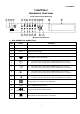
TABLE OF CONTENTS INDEX - TABLE OF CONTENTS------------------------------------------------------------------------------------------ 1 SETUP MENU LIST----------------------------------------------------------------------------------------------------------- 2 CHAPTER 1 INTRODUCTION / FEATURE-------------------------------------------------------------------------- 3 CHAPTER 2 HARDWARE OVERVIEW ------------------------------------------------------------------------------ 4 CHAPTER 3 SETUP PROCEDUR
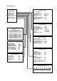
SETUP MENU List SETUP MENU SYSTEM SETUP SYSTEM SETUP CAMERA SETUP RECORD SETUP ALARM SETUP SCHEDULE RECORD EVENT LIST HDD MANAGEMENT DEAFULT SETUP EXIT DVR ID NUMBER SET TIME/DATE TIME DISPLAY MODE TIME DISPLAY LANGUAGE SELECT KEY LOCK MENU SETUP PROTECTION CHANGE PASSWORD SYSTEM SELECT EXIT 1 YY/MM/DD ON ENGLISH OFF OFF NTSC CAMERA SETUP CAMERA SELECT CAMERA RECORD MOTION SENTSITIVITY MOTION AREA SETUP BRIGHTNESS CONTRAST HUB CAMERA TITLE EDIT EXIT EVENT LIST HARD DRIVER: MASTER START TIME: 2005/MAY
CHAPTER 1 INTRODUCTION This product is 4 cameras input appliance with multiple function which will bring you following features: z z z z z z z z z z z z z z z z z z z z z z z z z z z z Device can be performed as VHS system with live display, play back and video recording. Device operates in hardware base with no OS (operating system) necessary for more reliability and stability.
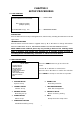
a11633RM4F17 CHAPTER 2 Hardware Overview Front Panel Layout Overview 1 2 3 4 5 6 7 8 9 Copy 1 2 3 4 10 20 17 21 22 23 POWER REC PLAY Quad H.D.D MENU Rec Digital Video Recorder Rew Search Stop Pause F.Fwd Search ENTER Play 11 12 13 14 15 16 18 19 Buttons Function List 1. DVR ESSENTIAL OPERATION Part Label 1 POWER 2 REC Recording status LED. 3 PLAY Playback status LED. 4 H.D.D H.D.D LED 5 6 7 8 9 10 11 12 13 REC Function Power status LED.
14 15 16 Pause F.Fwd Search PLAY Press Pause to pause (field by field) for forward. Press F. Fwd to play video forward at high speed. Press the button again the speed will be change circulative from ×2,×4, to the highest ×8. Press the Play button to into time search and play video forward. 17 ▲ 1. Move the cursor upward or decrease the number. 2. When it's not under recording mode, you can use the button to adjust position of date & time display which appears on OSD. 18 ▼ 1.
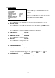
Back Panel Layout Overview 24 25 26 27 30 28 29 31 33 32 34 35 2. Back Panel Components Function List Part Label Function 24 ETHERNET Reserved 25 LED Reserved 26 COM PORT COM port for RS-485 interfaces which upon to request. 27 RS-485 header 4 pin Terminal. For external control of unit. 28 CAMERA OUT Camera 1-4 video output with BNC connector. 29 CAMERA IN Camera 1-4 video input with BNC connector. 30 MONITOR OUT Composite video output with 2 BNC connectors.
CHAPTER 3 SETUP PROCEDURES 0. LIVE VIEWING REC 30P 2005/MAY/16 10:20:30 MON Å---- STATUS BAR MOT [CAM1]O O[CAM2] [CAM3]O O[CAM4] [M] 231GB/239GB 97% [S] N/A Å---- INFORMATION BAR STATUS BAR Press ▲ button move from top or downgrade a line, and how many recording FPS will show on the left upper corner. INFORMATION BAR Press ▼ button move from bottom or upgrade a line, by ◄ or ► button to change information between HARD DISK STSTUS, RECORDING MODE and AUDIO RECORDING STATUS.
2. SYSTEM SETUP SYSTEM SETUP DVR ID NUMBER SET TIME/DATE TIME DISPLAY MODE TIME DISPLAY LANGUAGE SELECT KEY LOCK MENU SETUP PROTECTION CHANGE PASSWORD SYSTEM SELECT EXIT Press ▲ or ▼ key on "SYSTEM SETUP" & ◄ or ► 1 to enter: YY/MM/DD ON ENGLISH OFF OFF Use the ▲ or ▼ button to select items. Press the ◄ or ► button to confirm the selection. Press MENU back to SETUP MENU. NTSC 1. DVR ID NUMBER 1~32 Use W or X button to set up DVR ID for extension keyboard. Range from 1 to 32. 2.
3. CAMERA SETUP CAMERA SETUP CAMERA SELECT CAMERA RECORD MOTION SENTSITIVITY MOTION AREA SETUP BRIGHTNESS CONTRAST HUB CAMERA TITLE EDIT EXIT Press ▲ or ▼ key on "CAMERA SETUP" & ◄ or [CAM1] ON 1[MIN] ► to enter: STANDARD STANDARD STANDARD Press the ◄ or ► button to confirm the 1. CAMERA SELECT Use the ▲ or ▼ button to select items. selection. Press MENU back to SETUP MENU. CAM1/CAM2/CAM3/CAM4 Use ◄ or ► button to select the camera from CH1 – CH4 to be adjusted. 2.
4. RECORD SETUP RECORD SETUP RECORD MODE NORMAL RECORD FPS ALARM RECORD FPS ALARM RECORD DWELL RECORD QUALITY MOTION MIGRATION EXIT Press ▲ or ▼ key on "RECORD SETUP" & ◄ or MUX 30P 30P 10SEC HIGH ON ► to enter: Use the ▲ or ▼ button to select items. Press the ◄ or ► button to confirm the selection. Press MENU back to SETUP MENU. 1. RECORD MODE MUX/QUAD Use ◄ or ► button to select MUX (multiplexer) or OD (QUAD) recording.
5. ALARM SETUP ALARM SETUP [BUZZER] BUZZER DWELL VIDEO LOSS ALARM MOTION ALARM EXTERNAL ALARM 5SEC ON OFF ON [RELAY] VIDEO LOSS ALARM MOTION ALARM EXTERNAL ALARM ON ON ON Press ▲ or ▼ key on "ALARM SETUP" & ◄ or ► to enter: Use the ▲ or ▼ button to select items. Press the ◄ or ► button to confirm the selection. Press MENU to go back to SETUP MENU. EXTERNAL SENOR SETUP ALARM DISPLAY MODE OFF EXIT [BUZZER] 1.
6. SCHEDULE RECORD Press ▲ or ▼ key on "SCHEDULE RECORD" & ◄ SCHEDULE SETUP 0 3 6 9 12 15 18 or ► to enter: 21 24 Use the ◄ or ► button to select items. Press the ▲ or ▼ button to confirm the [RIGHT,LEFT] TO MOVE [MENU TO EXIT] [UP,DOWN] TO SELECT selection. Press MENU to go back to SETUP MENU. There are 24 circles in the schedule table, which represent 24 hours.
Record setup "MOTION EVENT MIGRATION" must at ON. In the period of alarm record triggered constantly that the a single EVENT LIST item will be extend while lapsed, thus ENET LIST would show the first triggered channel number on the list and the recording seconds will be extended . 8.
HARD DISK FORMATTED Otherwise, the following error message will be displayed on the screen: PASSWORD INCORRECT! CHANGE PASSWORD: Please refer to page 2 SYSTEM SETUP ->CHANGE PASSWORD. 6. SLAVE HDD CAPACITY N/A The slave HDD capacity sign will be indicated on the screen, it can't be revised. HDD N/A is with no HDD. 7. SLAVE HDD LEFT RATIO N/A The slave HDD left ratio sign will be indicated on the screen, it can't be revised. HDD N/A is with no HDD. 8. SLAVE HDD FORMAT Same with MASTER HDD FORMAT.
9. LOAD DEFAULT DEAFULT SETUP SET FOR ALL SYSTEM SETUP CAMERA SETUP RECORD SETUP ALARM SETUP EXIT Press ▲ or ▼ key on "DEAFULT SETUP" & ◄ or ► to OFF OFF OFF OFF OFF 1. SET FOR ALL enter: Use the ◄ or ► button to select items. Press the ▲ or ▼ button to confirm the selection. Press MENU back to SETUP MENU. ON/OFF Use W or X button to change all item in ON , OFF or "---" by individual 2. SYSTEM SETUP ON/OFF Use W or X button to ON for restore to default setting or OFF. 3.
CHAPTER 4 OPERATION PROCEDURES 1 Getting Started with your machine Please assure the following instructions before you switch on the machine: 1.1 Voltage check: Before power cable is connected, please check the voltage of this appliance against the supply. Input voltage range 100~240V, frequency range 47-63Hz. CAUTION - Damage would be caused if incorrect power voltage applied. 1.2 Hard Disk connection: Make sure the 40-Pin Hard Disk Data cable and the 4-Pin power connectors are properly connected.
3.1 Time Search: TIME SEARCH HDD1: MASTER START TIME: 2005/MAY/04 08:00:00 ^ HARD DRIVE: MASTER START TIME:2005/MAY/03 08:12:03 END TIME:2005/MAY/04 10:10:55 HARD DRIVE: SLAVE START TIME:N/A END TIME:N/A [RIGHT/LEFT] TO MOVE [UP/DOWN] TO CHANGE [PLAY] TO PLAY [QUAD] CHANGE HDD [MENU] EXIT When entered "TIME SEARCH" mode, by QUAD key change hard disk, screen will indicates the earliest record on corresponding hard drive with title "START TIME" and "END TIME".
3.3 Several ways to perform playback: 3.3.1 Press ►PLAY button to play video forward. 3.3.2 "PLAY" sign will be indicated in top left corner on the screen. "MUX or QUAD" sign will be indicated in top right corner on the screen, it means the recording mode you selected. 3.3.3 When playback reaches the vary end of record and "END"will appear. Press Rew Search button to play video reverse at 16 times speed fast rewind mode. F.Fwd Search button to play video forward at high speed. Press 3.3.
4 Hard disk Maximum 2 pieces and at lease one hard disk should be connected, the capacity of hard disk from 40GB to 400GB for each.
7 External alarm connector External alarm functions only when DVR has been set under recording mode. 4 input ports to receive signals from external alarm and GND port for termination. When external alarm is triggered, currents will be grounded through GND port to activate the external alarm. a. Texts "ALM" will be displayed on OSD corresponding channel. b. Relay action. c. Recording speed will be switch from normal mode to alarm mode (refer to chapter 4 about recording setting). d.
8 VGA Output VGA output is optional, please ensure that you have proper DVR model for VGA out put installation.
9 RS-485 control protocol Data format Data: 1 Byte / Parity: None / Start bit: 1 / Baud: 9600 Totally 3 bytes in data frame: 1. Byte=0x10 :Broadcasting DVR Byte=0x80+ID Number 2. Byte=Refer to below table :Remote Control DVR (ID number range: 5~21) :Command for each key string 3.
CHAPTER 5 SPECIFICATIONS Image System Resolution NTSC PAL Display 720×480 720×576 Record 640×224 640×272 Video Input BNC × 4 Video Looping output BNC × 4 Video Output BNC × 2 Audio Input (option) RCA × 1 Audio Output (option) RCA × 1 Display Frame Recording Frame Rate (QUAD) Recording Frame Rate (MUX) 4 × 30 fields/sec 4 × 25 fields/sec Max 30 fps Max 25 fps Max 30 / 4 fps Max 25 / 4 fps Storage Media Max 2 IDE Hard Disks / 1 Hard Disk & 1 CDRW Image Format M-JPEG Compress Rate
CHAPTER 6 RECORDING TIME LENGTH Recording time length is related to recording speed and recording quality. Tables below are offered for your reference. Record Mode=MUX Record Mode=QUAD Recording length under quad mode will shorter than multiplex mode and PAL will shorter than NTSC. 80GB H.D.
CHAPTER 7 HARD DRIVE INSTALLATION PROCEDURES 1. Hard drive jumpers need to be set properly in order to make DVR function correctly. 2. Instructions below are for second hard drive installation. If you prefer to have only one drive, please ignore instruction below. Remove DVR top cover by taking out screws from location shown below: ① . ② ④ ③ ⑤ ⑥ 3. Below picture indicates DVR which one without a H.D.D installed. 4.
5. Hooking up IDE cable and power cable to the hard drive as picture below, please take a note on that the red line on IDE cable must be next to power cable in order to have correct instillation. 6. This DVR supports maxima 2 hard drives, please take a note on cable length that you use to hook up with the hard drive. 7. Restore top cover then hook up with power and monitor a hard drive status message will appear if it's been installed successful. 8.
27 a11633RM4F17