Electric Control Valves/ Controller with Electric Actuator Type 3222/5724, Type 3222/5725 and Type 3222/5757 Type 3222/5725 Globe Valve mounted on Controller with Electric Actuator Type 3222/5757 Globe Valve mounted on Controller with Electric Actuator Mounting and Operating Instructions EB 5766 EN Edition July 2008
Contents Contents Page 1 1.1 1.2 Design and principle of operation . . . . . . . . . . . . . . . . . . . 4 Versions . . . . . . . . . . . . . . . . . . . . . . . . . . . . . . . . 4 Technical data . . . . . . . . . . . . . . . . . . . . . . . . . . . . . 6 2 2.1 2.2 2.3 Installation . . . . . . . . . . . Mounting position . . . . . . . Strainer . . . . . . . . . . . . Additional installation instructions 3 3.1 3.2 Attaching the actuator to the valve . . . . . . . . . . . . . . . . . .
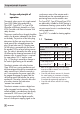
General safety instructions General safety instructions 4 The control valves may only be mounted, started up or serviced by fully trained and qualified personnel, observing the accepted industry codes and practices. Make sure employees or third persons are not exposed to any danger. All safety instructions and warnings in these mounting and operating instructions, particularly those concerning assembly, start-up and maintenance, must be observed.
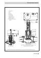
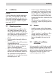
Design and principle of operation 1 Design and principle of operation The control valves consist of a single-seated Type 3222 Globe Valve and either a Type 5757, Type 5757-7 or Type 5724 Controller with Electric Actuator or a Type 5725 Controller with Electric Actuator with safety function. The process medium flows through the globe valve in the direction indicated by the arrow on the body.
Design and principle of operation 1 2 3 4 5 6 7 8 10 Valve body Seat Plug Plug stem Valve spring Guide nipple Balancing bellows Balancing piston Controller with electric actuator Type 3222/5757 Type 3222/5724 Special version for temperatures up to 200 °C and with plug balanced by a bellows Fig.
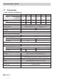
Design and principle of operation 1.2 Technical data 1. Single-seated Type 3222 Globe Valve Nominal size DN 15 20 25 32 40 50 Version with threaded ends with flanges as flanged body • • • • • • G ½ ¾ 1 – – – • • • – – – Thread size Version with female thread Nominal pressure PN 25 Metal sealing for KVS ≤ 2.5 · Soft sealing for KVS ≥ 3.6 Seat/plug sealing Rated travel mm 6 12 Rangeability 50 : 1 Class I (< 0.05 % of KVS coefficient) Leakage class acc.
Design and principle of operation Nominal size Thread size DN 15 20 25 32 40 50 G ½ ¾ 1 – – – 3.6 5.7 7.2 – – – 4 6.3 8 16 20 25 – – – KVS coefficients Version with female thread Version with male thread 0.1· 0.16 · 0.25 · 0.4 0.63 · 1.0 · 1.6 · 2.5 Reduced KVS coefficients Rated travel 1) 2) 3) 4) 5) 6) mm 1.0 · 1.6 · 2.5 4 5) · 3.
Design and principle of operation 2.
Installation 2 Installation Caution! Versions designed to handle temperatures up to 200 °C must be fitted with the dark gray graphite supplied with the valve. Do not use the UDP seals available as accessories as they are only suitable for temperatures up to 150 °C. 2.
Attaching the actuator to the valve 3 Attaching the actuator to the valve If the actuator has not already been mounted on the valve by the manufacturer or when the original actuator on a valve is to be replaced with a controller with electric actuator, proceed as follows. Note! Fasten the actuator and valve together either at the valve connection or at the intermediate insulating piece, depending on the valve version, with a tightening torque of 20 Nm. 3.
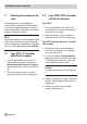
Electrical connections 4 Electrical connections Upon installing the electrical cables, you are required to observe the regulations concerning electrical power installations according to DIN VDE 0100 as well as the regulations of your local power supplier. Use a suitable power supply to ensure that no dangerous voltages from the system or parts of the system reach the device in standard operation or in case of a fault.
Electrical connections AS 230 V, 50 Hz Domestic hot water heating in instantaneous heating system: The electric wiring options are the same as for the Type 5757 Controller with Electric Actuator, (see section 4.2). In addition, the pump control output can be configured as a fault alarm output.
Manual override 5 Type 5725 Manual override The direction of action and travel can be read off the travel indication scale. 5.1 Type 5757/-7 Controller with Electric Actuator Caution! Only activate the handwheel when the actuator is disconnected from the power supply. 4 Turn handwheel clockwise to extend the actuator stem 4 Turn handwheel counterclockwise to retract the actuator stem 5.2 Type 5724/5725 Controller with Electric Actuator Type 5724 Adjust the travel by turning the handwheel (approx.
Operation 6 Operation The controllers with electric actuators are adapted to the required control task by configuration and parameterization performed in TROVIS-VIEW Operator Interface: 4 Type 5757-7: TROVIS-VIEW 6661-1066 4 Type 5757: TROVIS-VIEW 6661-1062 4 Type 5724 and Type 5725: TROVISVIEW 6661-1060 Note! Instructions on how to operate the TROVIS-VIEW Operator Interface as well as on the function and parameter settings are contained in the Mounting and Operating Instructions EB 5757-7 EN, EB 5757
Maintenance 7 Maintenance The control valve is subject to natural wear. Depending on the conditions the valve is operated in, it needs to be checked at regular intervals. If leakage to the atmosphere occurs, remove the valve from the pipeline and replace the damaged parts. Warning! For maintenance work on the valve, make sure the relevant section of the pipeline is depressurized and, depending on the process medium, drained as well.
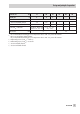
Dimensions in mm and weights 8 Dimensions in mm and weights Nominal size DN 15 20 25 32 40 G ½ ¾ 1 – – – Ød 21.3 26.8 33.7 42 48 60 R G 2½ Thread size Pipe Thread size 50 G¾ G1 G 1¼ G 1¾ G2 SW 30 36 46 59 65 82 L 65 70 75 100 110 130 Length with welding ends L1 210 234 244 268 294 330 Height H2 Width across flats Length Versions for temperatures up to 200 °C and with intermediate insulating piece Height H3 Weight without actuator 45.
Dimensions in mm and weights Weights of controllers with electric actuators Type Weight without valve, approx. kg 5757/-7 5724 5725 0.7 1.1 1.3 Intermediate insulating piece Type 3222/5757(-7), only up to DN 25 Types 3222/5724 Types 3222/5725 Version with flanges Version with threaded ends Flanged valve body version Version with female thread Fig.
Appendix 9 Appendix 9.1 Wiring for Type 5757-7 (refer to EB 5757-7 EN) Note! The pump output L´ is non-floating (230 V~).
Application with flow, return flow, and outdoor sensors as well as a potentiometer for adjusting the set points RüS VS AS 1 F01 - 1 Outdoor sensor 0 F02 - 0 Potentiometer/binary input 0 F05 - 1 Pt 1000 Control w.
Appendix 9.
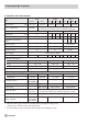
Appendix Operation with Pt 1000 sensor and flow switch Functions WE Configuration Hot water tapping recognition 1 F01 - 1 Flow switch 1 F02 - 0 Current input 0 F05 - 0 Pt 1000 BE22) 5V or Operation with Pt 1000 sensor and external set point over an mA signal Functions WE Configuration Hot water tapping recognition 1 F01 - 0 Current input 0 F05 - 0 Current input function 0 F06 - 1 br 230V, 50Hz GND ye rd gr + 4(0)...
Appendix 9.
Appendix Operation with Pt 1000 sensor and flow switch Pt 1000 Functions WE Configuration Hot water tapping recognition 1 F01 - 1 Flow switch 1 F02 - 0 Current input 0 F05 - 0 3) BE22) 230V, 50Hz L1 L N S1 S2 S1 5V IN 4) Mechanical engineering applications Operation with Pt 1000 sensor and external set point over an mA signal input Functions WE Configuration Hot water tapping recognition 1 F01 - 0 Current input 0 F05 - 0 Current input function 0 F06 - 1 + 4(0) ...
EB 5766 EN 2008-11 SAMSON AG · MESS- UND REGELTECHNIK Weismüllerstraße 3 · 60314 Frankfurt am Main · Germany Phone: +49 69 4009-0 · Fax: +49 69 4009-1507 Internet: http://www.samson.