
Automobile Parts User Manual

2 Installation
Caution!
Versions designed to handle temperatures
up to 200 °C must be fitted with the dark
gray graphite supplied with the valve. Do
not use the UDP seals available as accesso
-
ries as they are only suitable for tempera
-
tures up to 150 °C.
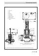
2.1 Mounting position
4
Choose the place of installation where
the ambient temperature does not ex
-
ceed or fall below the permissible limits
specified for the actuator and that allows
you to freely access the control valve
even after the entire plant has been com-
pleted.
4
Flush the pipeline thoroughly before in-
stallation.
4
Do not install the valve with the actuator
suspended downwards.
Install versions for water and steam up to
200 °C with the actuator installed up
-
right in a horizontal pipeline.
4
If you wish to insulate the control valve,
install an intermediate insulating piece
between valve and actuator. Make sure
the insulation ends 25 mm above the
valve body. Do not insulate the actuator
and coupling nut as well.
4
Install a strainer (SAMSON Type 2 NI)
upstream of the control valve to prevent
any sealing parts, weld spatter or other
foreign matter carried along by the pro
-
cess medium from impairing the proper
functioning of the valve, in particular, the
tight shut-off.
4
The valve must be installed free of stress.
If necessary, support the piping near the
connections.
2.2 Strainer
4
Install the strainer with the filter element
facing downwards upstream of the valve
inlet.
4
Choose the place of installation to allow
enough space to remove the filter.
4
Install the strainer with the direction of
flow as indicated by the arrow on the
body.
2.3 Additional installation
instructions
We recommend to install a hand-operated
shut-off valve both upstream of the strainer
and downstream of the control valve to be
able to shut down the plant for cleaning and
maintenance, and when the plant is not
used for longer periods of time.
EB 5766 EN 9
Installation