Automation System 5400 Heating and District Heating Controller TROVIS 5476 Mounting and Operating Instructions EB 5476 EN ® Electronics from SAMSON Firmware version 2.
Disclaimer of liability Disclaimer of liability We are constantly developing our products and therefore, reserve the right to change the product or the information contained in this document at any time without notice. We do not assume any liability for the accuracy or completeness of these mounting and operating instructions. Moreover, we do not guarantee that the buyer can use the product for an intended purpose.
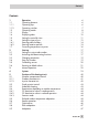
Contents Contents 1 1.1 1.1.1 1.1.2 1.2 1.3 1.4 1.5 1.6 1.6.1 1.6.2 1.7 Operation . . . . . . . . . . . . . . . . . . . . . . . . . . . . . . . 6 Operating elements . . . . . . . . . . . . . . . . . . . . . . . . . . . 6 Operating keys . . . . . . . . . . . . . . . . . . . . . . . . . . . . . 6 Operating switches . . . . . . . . . . . . . . . . . . . . . . . . . . . 7 Operating modes . . . . . . . . . . . . . . . . . . . . . . . . . . . . 8 Display. . . . . . . . . . . . . . . . . . . . . . . . . . . . .
Contents 5.10 5.11 Pump management . . . . . . . . . . . . . . . . . . . . . . . . . . 48 Potentiometer input . . . . . . . . . . . . . . . . . . . . . . . . . . 48 6 6.1 6.2 6.3 6.4 6.5 6.6 6.7 6.8 6.9 6.9.1 6.9.2 6.10 6.11 Functions of the DHW circuit. . . . . . . . . . . . . . . . . . . DHW heating in the storage tank system . . . . . . . . . . . . . DHW heating in the storage tank charging system . . . . . . . . DHW heating with solar system (Anl 2, 3, 4, 5 und 9) . . . . . .
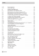
Contents 9.1 9.2 9.3 9.4 9.4.1 9.4.2 9.5 Controller with RS-232-C port . . . . . . . . . . . . . Controller with serial RS-485 interface . . . . . . . . . Description of communication parameters to be adjusted Meter bus interface . . . . . . . . . . . . . . . . . . Activating the meter bus . . . . . . . . . . . . . . . . Flow rate and/or capacity limitation via meter bus . . . Memory module. . . . . . . . . . . . . . . . . . . . . . . . . . . . . . . . . . . . . . . . . . . . . . . . . . . . . . . .
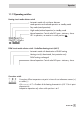
Operation 1 Operation The controller is ready for use with the temperatures and operating schedules preset by the manufacturer. On start-up, the current time and date need to be set at the controller (–> section 1.5). 1.1 Operating elements The operating controls are located in the front panel of the controller and protected by a Plexiglas door. 1.1.1 Operating keys Changeover key (–> Fig.
Operation 1.1.
Operation 1.2 Operating modes Day mode (rated operation) Regardless of the programmed times-of-use, the set points relevant for rated operation are used by the controller. Night mode (reduced operation) Regardless of the programmed times-of-use, the set points relevant for reduced operation are used by the controller. Automatic mode During the programmed times-of-use, the controller works in rated operation.
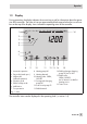
Operation 1.3 Display During operation, the display indicates the current time as well as information about the operation of the controller. The times-of-use are represented by black squares below the row of numbers at the top of the display. Icons indicate the operating status of the controller. 16 1 2 3 4 5 6 7 8 9 10 11 12 13 14 1 Automatic operation 8 Heating pump UP 2 Day mode (rated oper.
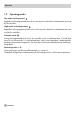
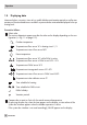
Operation 1.4 Displaying data Measured values, set points, times-of-use, public holidays and vacation periods as well as temperatures of the connected sensors and their set points can be retrieved and displayed in the operating level. Proceed as follows: Select value. The various datapoints appear one after the other on the display depending on the configuration (–> Fig. 11 on page 112).
Operation 1.5 Setting the controller time The current time and date need to be set immediately after start-up and after a power failure lasting longer than 24 hours. The time is set in the parameter level. Proceed as follows: 0 1 2 3 4 5 6 7 8 9 10 11 12 13 14 15 16 17 18 19 20 21 22 23 24 Switch to the parameter level. Display: Time, blinks Activate editing mode for the controller time. blinks. 1 Change controller time. Confirm controller time. Display: Date (day.month) Change date setting.
Operation 1.6 Setting the times-of-use Two times-of-use can be set for each day of the week. If only one time-of-use is required, the start and stop times of the second time-of-use must be programmed to identical times. The times schedules are set for the required control circuits one after the other in the parameter level.
Operation 0 1 2 3 4 5 6 7 8 9 10 11 12 13 14 15 16 17 18 19 20 21 22 23 24 Select datapoint for times-of-use. Display: 3 4 5 6 7 8 9 10 11 12 13 14 15 16 17 18 19 20 21 22 23 24 Activate editing mode for times-of-use.
Operation 1.6.1 Entering public holidays On public holidays, the times-of-use specified for Sunday apply. A maximum of 20 public holidays may be entered. The public holidays are set in the parameter level. Set the function block FB6 = ON to make the programmed public holidays also apply to the DHW heating. Parameter WE Range of value Public holidays – Configurable as required Proceed as follows: 0 1 2 3 4 5 6 7 8 9 10 11 12 13 14 15 16 17 18 19 20 21 22 23 24 Switch to the parameter level.
Operation 1.6.2 Entering vacation periods During vacation periods, the controller constantly remains in the reduced operating mode. The system is monitored for frost. A maximum of 10 vacation periods can be entered. The vacation periods are set in the parameter level. Set the function block FB6 = ON to make the programmed vacations also apply to the DHW heating.
Operation Deleting vacation periods: Select the vacation period you wish to delete in the datapoint for vacation periods. Confirm selection. Select – – – – . Delete vacation period. 1.7 Correcting temperature set points The room temperature for the heating circuit can be adapted to the actually valid conditions at the correction switch: 4 Slide correction switch in + direction: The flow temperature is increased and the room temperature becomes warmer.
Start-up 2 Start-up 2.1 Setting the system code number 10 different hydraulic schematics are available. Each system configuration is represented by a system code number (Anl). The different schematics are dealt with in section 4. Available controller functions are described in sections 5, 6 and 7. Changing the system code number resets previously adjusted function blocks to their default settings (WE). Function block parameters and settings in the parameter level remain unchanged.
Start-up Proceed as follows: Switch to the parameter level. Display shows: Time, blinks Switch to the configuration level. Display shows: Current system code number, blink. Select level displaying function blocks 0 to 23 or Select level displaying function blocks 24 to 47. Select function block. Activate editing mode for function block. The function block number starts to blink. If 0 0 0 0 0 appears on the display, the key number needs to be entered first. Refer to section 2.
Start-up 2.3 Changing parameters Depending on the set system code number and the activated functions, not all parameters listed in the parameter list in the Appendix (–> section 12.2) might be available. Proceed as follows: Switch to the parameter level. Display shows: Time, blinks Select parameter. Activate editing mode for parameter. Parameters which do not allow the editing mode to activated are protected by a key number.
Start-up 2.5 Calibrating sensors The connected sensors are calibrated in the configuration level. The following applies: 4 FB16 = ON, select “P1000“: 4 FB16 = ON, select “ntc“: 4 FB16 = OFF: Pt 1000 and Pt 100 sensors NTC and Pt 100 sensors PTC and Pt 100 sensors (default setting) The resistance values of the sensors can be found on page 98.
Start-up Return flow sensor (RüF2) Solar circuit collector sensor (CF) Flow sensor (VF2) Storage tank sensor (SF1–SF2) Flow sensor in DHW circuit (VF3) Activate editing mode for sensor. Correct measured temperature. Read the actual temperature directly from the thermometer at the point of measurement and enter this value as the reference temperature. Confirm corrected measured temperature. Additional sensors are calibrated similarly. Exit the configuration level. Return to the operating level. 2.
Manual operation 3 Manual operation Heating circuit and DHW circuit (Anl 9: underfloor heating circuit) can be set to manual mode at their operating mode selector switches. Heating circuit mode selector switch The heating circuit can only be set to manual mode when the DHW/underfloor heating circuit mode selector switch is not positioned at .
Systems 4 Systems 10 hydraulic schematics are available. System code number (Anl) 1 Heating Outdoor temperature dependent flow temperature control with variable return flow temperature limitation 2 3 4 5 6 • Mixing control • From the primary circuit DHW heating 7 From the secondary circuit • in storage tank system • • 9* 11 • • • • • • • in st. tank charging system • 8 • • • • • • • • in instantaneous heating sys.
Systems System Anl 1 Default settings 24 EB 5476 EN FB13 = OFF Without RF FB20 = ON With RüF1
Systems System Anl 2 Default settings FB13 = OFF Without RF FB20 = ON With RüF1 FB14 = ON With SF1 FB15 = OFF Without SF2 EB 5476 EN 25
Systems System Anl 2, setting different from default setting · With switch valve Setting different from default setting: FB9 = ON, select “US“ 26 EB 5476 EN FB13 = OFF Without RF FB20 = ON With RüF1 FB14 = ON With SF1 FB15 = OFF Without SF2
Systems System Anl 2, setting different from default setting · With solar system Solar collector Setting different from default setting: FB15 = ON, select “CF“ FB13 = OFF Without RF FB20 = ON With RüF1 FB14 = ON With SF1 FB15 = ON, select “CF“ With SF2 EB 5476 EN 27
Systems System Anl 3 Default settings FB13 = OFF Without RF FB20 = ON With RüF1 FB14 = ON With SF1 FB15 = ON, select “---“ With SF2 FB27 = OFF 28 EB 5476 EN Without VF3
Systems System Anl 3, setting different from default setting · With solar system Solar collector Setting different from default setting: FB15 = ON, select “CF“ FB13 = OFF Without RF FB20 = ON With RüF1 FB14 = ON With SF1 FB15 = ON, select “CF“ With SF2 FB27 = OFF Without VF3 EB 5476 EN 29
Systems System Anl 4 Default settings 30 EB 5476 EN FB13 = OFF Without RF FB20 = ON With RüF1 FB21 = OFF Without RüF2
Systems System Anl 4, setting different from default setting · With solar system Solar collector Setting different from default setting: FB15 = ON FB13 = OFF Without RF FB15 = ON With SF2 FB20 = ON With RüF1 FB21 = OFF Without RüF2 EB 5476 EN 31
Systems System Anl 5 Default settings FB13 = OFF Without RF FB20 = ON With RüF1 FB14 = ON With SF1 FB15 = ON, select “---“ With SF2 FB21 = OFF 32 EB 5476 EN Without RüF2
Systems System Anl 5, setting different from default setting · With solar system Solar collector Setting different from default setting: FB15 = ON, select “CF“ FB13 = OFF Without RF FB20 = ON With RüF1 FB14 = ON With SF1 FB15 = ON, select “CF“ With SF2 FB21 = OFF Without RüF2 EB 5476 EN 33
Systems System Anl 6 Default settings 34 EB 5476 EN FB13 = OFF Without RF FB20 = ON With RüF1
Systems System Anl 7 Default settings FB13 = OFF Without RF FB20 = ON With RüF1 FB14 = ON With SF1 FB15 = OFF Without SF2 EB 5476 EN 35
Systems System Anl 8 Default settings 36 EB 5476 EN FB13 = OFF Without RF FB20 = ON With RüF1 FB14 = ON With SF1 FB15 = ON With SF2 FB27 = OFF Without VF3
Systems System Anl 9 Default settings FB13 = OFF Without RF FB20 = ON With RüF1 FB14 = ON With SF1 FB15 = OFF Without SF2 EB 5476 EN 37
Systems System Anl 9, setting different from default setting · With solar system Solar collector Setting different from default setting: FB15 = ON, select “CF“ 38 EB 5476 EN FB13 = OFF Without RF FB20 = ON With RüF1 FB14 = ON With SF1 FB15 = ON, select “CF“ With SF2
Systems System Anl 11 Default settings FB13 = OFF Without RF FB20 = ON With RüF1 FB14 = ON With SF1 FB15 = ON With SF2 FB21 = OFF Without RüF2 FB27 = OFF Without VF3 EB 5476 EN 39
Functions of the heating circuit 5 Functions of the heating circuit Which controller functions are available depends on the selected system code number (Anl). 5.1 Weather-compensated control When weather-compensated control is used, the flow temperature is controlled according to the outdoor temperature. The heating characteristic in the controller defines the flow temperature set point as a function of the outdoor temperature (–> Fig. 2).
Functions of the heating circuit Function WE Configuration Outdoor temperature – Current input OFF FB18 = ON 0: 0 to 20 mA = –20 to 50 °C 4: 4 to 20 mA = –20 to 50 °C 5.1.1 Gradient characteristic Basically, the following rule applies: a decrease in the outdoor temperature causes the flow temperature to increase. By varying the Gradient and Level parameters, you can adapt the characteristic to your individual requirements.
Functions of the heating circuit 5.1.2 4-point characteristic The 4-point characteristic allows you to define your own heating characteristic. It is defined by 4 points for the Outdoor temperature, the Flow temperature and the Return flow temperature. The Set-back difference at points 2 and 3 indicates how much the flow temperature is reduced outside the times-of-use. The Max. flow temperature and Min. flow temperature parameters mark the upper and lower limits of the flow temperature. P1 to P4 tVL tA ...
Functions of the heating circuit Parameters WE WE* Range of values Min. flow temperature 20 °C 20 °C 20 to 130 °C * 5.2 Default setting applies to system Anl 9, floor heating Fixed set point control During the times-of-use, the flow temperature can be controlled according to a fixed set point. Outside the times-of-use, this set point is reduced by the Set-back difference. Both Minimum flow temperature and Maximum flow temperature parameters are set to identical values.
Functions of the heating circuit 5.4 Deactivation depending on outdoor temperature 5.4.1 OT deactivation value in rated operation If the outdoor temperature during rated operation exceeds the limit OT deactivation value in rated operation, the affected heating circuit is put out of service immediately. The valve is closed and the pump is switched off after a lag time. When the outdoor temperature falls below this value (less 0.5 °C hysteresis), heating operation is restarted immediately.
Functions of the heating circuit Function WE Configuration Summer mode OFF FB3 = ON 01.06 30.09 18 °C Start summer mode / 01.01 to 31.12 Stop summer mode / 01.01 to 31.12 Outdoor temperature limit / 0 to 30 °C 5.5 Delayed outdoor temperature adaptation The calculated outdoor temperature is used to determine the flow temperature set point. The heat response is delayed when the outdoor temperature either decreases, or increases and decreases.
Functions of the heating circuit have been activated. Refer to page 78 onwards for the wiring diagrams of the room panels. Functions WE Configuration Room sensor RF OFF FB13 = ON Potentiometer input 1 to 2 kΩ OFF FB24 = OFF 5.7 Optimization This function requires the use of a room sensor.
Functions of the heating circuit 5.8 Flash adaptation The function is only active in automatic mode ( ). Direct reactions to deviations in room temperature can be achieved using the function block setting: FB2 = ON. A gradient characteristic (FB19 = OFF) must be configured. Flash adaptation counteracts room temperature deviations by increasing or decreasing the level of the heating characteristic by up to 5 °C. The corrections are made after 10 minutes by 1 °C.
Functions of the heating circuit 5.10 Pump management The Pump management function can be used for the heating circuit (circulation pump UP1).
Functions of the DHW circuit 6 Functions of the DHW circuit 6.1 DHW heating in the storage tank system SLP Storage tank charging pump SF1 Storage sensor 1 ZP Circulation pump KW Cold water WW Hot water Fig.
Functions of the DHW circuit DHW heating from the primary circuit (Anl 4): The control valve opens depending on the DHW temperature from its closed position. Stop storage tank charging The controller stops charging the storage tank when the water temperature in the storage tank measured at sensor SF1 reaches the value T = DHW heating ON + Hysteresis.
Functions of the DHW circuit 6.2 DHW heating in the storage tank charging system SF1 Storage tank sensor 1 SF2 Storage tank sensor 2 SLP Storage tank charging pump VF Flow sensor TLP Heat exchanger charging pump ZP Circulation pump KW Cold water WW Hot water Fig.
Functions of the DHW circuit Stop storage tank charging The controller stops charging the storage tank when the water temperature in the storage tank measured at sensor SF1 reaches the value T = DHW heating ON + Hysteresis. In systems with two storage tank sensors, the controller stops charging the storage tank when the water temperature in the storage tank measured at sensor SF2 reaches the value DHW heating OFF.
Functions of the DHW circuit 6.3 DHW heating with solar system (Anl 2, 3, 4, 5 und 9) The systems Anl 2, 3, 4, 5 and 9 include a solar system for DHW heating. In these systems, the difference between the temperatures measured at storage sensor SF2 and the sensor at the solar collector CF is determined. The Solar pump ON parameter determines the minimum temperature difference between sensors SF2 and CF required to activate the solar pump.
Functions of the DHW circuit 6.5 Circulation pump operation during storage tank charging With the setting FB26 = ON, the circulation pump continues operation according to the programmed time schedule even during storage tank charging. With the setting FB26 = OFF, the circulation pump is switched off as soon as the storage tank charging pump is activated. The circulation pump returns to operate according to the time schedule when the storage tank charging pump has been switched off again.
Functions of the DHW circuit Once a parallel pump operation cycle has been activated and the time for Stop parallel operation has elapsed, system deviations greater than 5 °C cause the controller to suspend parallel operation for 10 minutes and to apply priority operation.
Functions of the DHW circuit Set-back difference by set-back of the current flow temperature. The amount of time in which the priority for the DHW circuit is given is set in the Priority in case of deviation parameter. Function WE Configuration Priority for DHW circuit OFF FB8 = ON, Ab 10 min Priority in case of deviation / 2 to 10 min 6.10 Forced charging of the DHW storage tank (Anl 2, 3, 5, 7, 8 and 9) This function is always configured when the system has at least one storage tank sensor.
System-wide functions 7 System-wide functions 7.1 Automatic summer time/winter time changeover The clock is automatically adjusted on the last Sunday in March at 2.00h and on the last Sunday in October at 3.00h. Function WE Configuration Summer time/winter time changeover ON FB5 = ON 7.2 Frost protection When outdoor temperatures below 3 °C occur, the heating circulation pumps UP1 and UP2 are switched on. The controllers regulates the temperature to a flow temperature set point of 20 °C.
System-wide functions The measured temperature reading (return flow temperature) and the set point reading (flow temperature of the heating, charging temperature) blink to indicate that a return flow limitation is active in the control circuit concerned. In systems Anl 2, 3, 7, 8 and 9, the Return flow limitation temperature parameter during DHW heating is used for limitation in the primary circuit while the DHW heating is active.
System-wide functions 7.5 Condensate accumulation control Activate the Limitation of the system deviation for OPEN signal function to start up condensate accumulation plants, in particular to avoid problematic excess temperatures. The controller response to set point deviations which cause the primary valve to open is attenuated. The controller response to set point deviations which cause the control valve to close remains unaffected.
System-wide functions 7.7 On/off control The flow temperature can be controlled by an on/off signal. The controlled valve is opened when the flow temperature falls below the set point by T = 0.5 x Hysteresis. When the flow temperature exceeds the set point by T = 0.5 x Hysteresis, the control valve is closed. The greater the Hysteresis selected, the lower the switching frequency. Function WE Configuration On/off control for RK1/RK2 ON FB10/FB17 = OFF 5 °C Hysteresis / 1 to 30 °C 7.
System-wide functions Note! The function cannot be selected in systems Anl 4, 5 and 9 with solar system and in system Anl 11 with VF3. 7.10 Flow rate/capacity limitation Flow rate/capacity limitation can be implemented based on a pulse or standardized signal of 0/4 to 20 mA provided by the heat meter. This only applies in plants without solar system. Particularly when a standardized signal is applied, a heat meter (flow meter) with high measuring accuracy is required.
System-wide functions Functions WE Configuration Current input for flow rate measurement OFF FB22 = OFF Flow rate or capacity limitation OFF FB23 = ON Max. limit / 3 to 500 pulse/h Limiting factor / 0.1 to 10 Max. limit for DHW / 3 to 500 pulse/h Limiting factor / 0.1 to 10 500 pulse/h 1.0 500 pulse/h 1.0 7.10.
System-wide functions switches were set to “Night mode” or Heating circuit(s) deactivated” or “DHW heating unchanged”. Function WE Configuration Locking manual levels OFF FB34 = ON 7.12 Setting a customized key number Switch to the parameter level. Display shows: Time, blinks Switch to the configuration level. Display shows: Currently valid system code number, blink Select a function block (e.g. FB20) protected by the key number. Open the function block. 0 0 0 0 0 appears on the display.
Operational faults 8 Operational faults Malfunctions or faults are indicated by the 8.1 icon blinking on the display. Sensor failure The following list explains how the controller responds to the failure of the different sensors. Safety functions such as frost protection and excess temperature protection no longer work when a sensor fails. Outdoor sensor AF: When the outdoor sensor fails, the controller uses a flow temperature set point of 50 °C or the Max. flow temperature (when the Max.
Operational faults 8.3 Temperature monitoring Should a deviation arise in a control circuit that is greater than 10 °C for longer than 30 minutes, the bit D12 is automatically set in the error status register. If this function is not required, configure FB36 = ON, select “steig“ and leave the input BE8 unswitched. 8.4 Error status register The error status register is used to indicate controller or system errors.
Communication Example of a transfer to the control system: The error status register is transferred as a word in a holding register (HR) whose value is calculated as follows: = D_0 + D_1 + … + D_15 = 20 + 21 + … + 215 9 Communication Using the serial system bus interface, the TROVIS 5476 Heating Controller can communicate with a building control system. In combination with a suitable software for process visualization and communication, a complete control system can be implemented.
Communication 9.1 Controller with RS-232-C port The system bus connection is located at the back of the controller housing (RJ-12 jack). In this case, the controller can be connected either directly to the serial interface of a PC (point-to-point connection) or to a (dial-up) modem. A dial-up modem is required if the controller is to be connected to the telecommunications network.
Communication Functions WE Configuration Modem operation OFF FB44 = ON 8 bit 30 min 5 min 5 min PULS – 8 bit/16 bit Cyclical initialization In* / 0 to 255 min Dialing pause to GLT PA* / 0 to 255 min Modem timeout t0* / 0 to 99 min Dial procedure / PULS/ton Phone no.
Communication If you wish to use more than 32 devices in line or need to bridge greater distances, make sure repeaters (e.g. TROVIS 5482) are installed to replicate the signal. With 8-bit addressing, a maximum of 246 devices can be addressed and connected to a bus. ! Warning! You are required to follow the relevant standards and regulations concerning lightning and overvoltage protection on installation.
Communication Modem time-out (t0) When the controller connects to the GLT but without addressing a Modbus data point, the connection is closed after the time specified for Modem time-out has elapsed. If the error status register has not been read during the GLT connection, the controller dials up to the GLT again after the Dialing pause to the control station (PA) has elapsed.
Communication Note! A 15 V DC supply voltage (+15 V at terminal 15 connected to the meter bus connection terminal 3) can be used at the WMZ connection of TROVIS 5476 Controller when the red jumper on the back of the controller is located pointing towards the edge of the controller (Fig. 8). Otherwise, the meter bus module in the heat meter is supplied.
Installation for details on which listed heat meters fulfill this criterion and can be used for limitation purposes. In case of battery-operated heat meters in particular, please note that some makes react with communication intervals if they are polled too frequently. Other makes could use up their batteries too quickly. The technical documentation TV-SK 6311 provides more details on these matters. 4 A system with simultaneous room heating and DHW heating requires maximum energy.
Appendix Function WE Configuration Flow rate limitation OFF FB30 = ON m3 2.0 m 2.0 m 2.0 m 2.0 1.0 3 h 3 3 At/--m Maximum limit / 0.01 to 650 h m Maximum limit for heating* / 0.01 to 650 m Maximum limit for DHW / 0.01 to 650 h m Minimum limit/ 0.01 to 650 h Limiting factor / 0.1 to 10.0 3 h h h 3 3 3 * Maximum limit for heating, points 1 to 4 * Does not need to be set on selecting “At“ WE Parameter* h Range of values 3 2.0 m /h 0.
Installation Parameter* * WE Range of values Parameter only needs setting with FB31 = ON, select “At“ 9.5 Memory module The use of a memory module (accessory no. 1400-7142) is particularly useful to transfer all data from one TROVIS 5476 Controller to several other TROVIS 5476 Controllers. The memory module is plugged into the RJ-12 jack integrated into the front panel. Once the module has been connected, “76 SP“ is displayed.
Installation Panel mounting 2 1 Back of the controller 2 Controller housing Wall mounting Top hat rail mounting Dimensions in mm: W x H x D = 144 x 96 x 125 Fig.
Electrical connection 11 Electrical connection ! Caution! For electrical installation, you are required to observe the relevant electrotechnical regulations of the country of use as well as the regulations of the local power suppliers.
Electrical connection Connecting the sensors Cables with a minimum cross-section of 2 x 0.5 mm² can be connected to the terminals at the back panel of the housing. Connecting the actuators Connect cables with at least 1.5 mm² suitable for damp locations to the terminals of the controller output. The direction of travel needs to be checked at start-up. Set slide switch to (+). Valves must open. Set slide switch to (–). Valves must close. 4 4 Connecting the pumps Connect all cables with at least 1.
Electrical connection Systems Anl 1 to 3 Potentiometer 1 to 2 kΩ 1) 2) Free For 0 to 20 mA 50 Ω connected in parallel Option: Type 5244 Type 5257-5 System Anl 4 Potentiometer 1 to 2 kΩ 1) 2) Free For 0 to 20 mA 50 Ω connected in parallel Option: Type 5244 Type 5257-5 78 EB 5476 EN
Electrical connection Systems Anl 5 to 7 Potentiometer 1 to 2 kΩ 1) Free 2) For 0 to 20 mA 50 Ω connected in parallel Option: Type 5244 Type 5257-5 System Anl 8 Potentiometer 1 to 2 kΩ 1) 2) Free For 0 to 20 mA 50 Ω connected in parallel Option: Type 5244 Type 5257-5 EB 5476 EN 79
Electrical connection System Anl 9 Potentiometer 1 to 2 kΩ 1) Free 2) For 0 to 20 mA 50 Ω connected in parallel Option: Type 5244 Type 5257-5 System Anl 11 Potentiometer 1 to 2 kΩ 1) Free 2) For 0 to 20 mA 50 Ω connected in parallel Option: Type 5244 Type 5257-5 80 EB 5476 EN
Appendix 12 Appendix 12.1 Function block list FB Function WE Anl Comments 0 Optimization OFF FB0 = ON: Optimization active; when FB0 = ON also FB13 = ON 1 Adaptation OFF FB1 = ON: Adaptation active; when FB1 = ON also FB13 = ON 2 Flash adaptation OFF FB2 = ON: Flash adaptation active; when FB2 = ON also FB13 = ON 3 Summer mode OFF FB3 = ON: Summer mode active Function block parameters: Start summer mode / 01.01 to 31.12 (01.06) End summer mode / 01.01 to 31.12 (30.
Appendix FB Function WE 9 OFF 2, 3, FB9 = ON: Parallel pump operation 9 Select (Anl 2 and 9): PU: Parallel pump operation US: Operation with switchover valve Parallel pump operation Anl Comments Function block parameter (on selecting: US): Stop parallel oper.
Appendix FB Function WE Anl Comments 16 Sensor selection OFF All FB16 = ON; select: P1000: Pt 1000 and Pt 100 sensors* ntc: NTC and Pt 100 sensors* FB16 = OFF: PTC and Pt 100 sensors* * A mixture of both types of sensor is possible 17 Control mode three-step RK2 ON 4, 5, 6, 7, 8, 9, 11 FB17 = ON: Three-step signal control mode Function block parameters: KP (proportional gain) / 0.1 to 50 (0,5) TN (reset time) / 1 to 999 s (Anl 5, 6: 60 s; Anl 4: 200 s) TY (val.
Appendix FB Function WE Anl Comments 22 Current input for flow rate measurement OFF All FB22 = ON: Current input active Select: 0: 0 to 20 mA signal feedforwarding 4: 4 to 20 mA signal feedforwarding A 50-Ω resistor must be connected to terminals 15 (+) and GND (terminals ½) in parallel to the current signal FB22 = OFF: Pulse input active Setting only possible after entering key number! 23 Flow rate or capacity limitation OFF All FB23 = ON and FB22 = OFF: Limitation with pulse input Function block
Appendix FB Function WE Anl Comments 29 Meter bus (5) OFF All FB29 = ON: Meter bus communication activated Function block parameters WMZ 1 to 3: Meter bus address / 0 to 255 (WMZ1: 254; WMZ2, 3: 255) Model code / 1434, CAL3, APAtO, SLS (1434) Reading mode / 24h, Cont CoiL (Cont) Setting only possible after entering key number! 30 Flow rate limitation OFF (6) All FB30 = ON: Flow rate limitation activated Select: At: Outdoor temperature dependent limitation, FB19 = ON when “At“ selected ---: Fixed lim
Appendix FB Function WE 36 BE8 (12) to to 43 (19) BE1 44 Modem operation (20) Anl Comments All FB36 to 43 = ON: Binary input in error status register Select: StEIG: Fault indicated by rising edge/make contact FALL: Fault indicated by negative edge/break contact OFF All Select: 8-bit: 8-bit addressing 16-bit: 16-bit addressing FB44 = ON: Modem function activated Function block parameters: Cyclical initialization In / 0 to 255 min (30 min) Intervals between dialing PA / 0 to 255 min (5 min) Modem timeou
Appendix 12.2 Parameter list Parameter designation Range of values (default values) Display 0 1 2 3 4 5 6 7 8 9 10 11 12 13 14 15 16 17 18 19 20 21 22 23 24 Gradient, flow 0.2 to 3.2 (1.
Appendix Parameter designation Range of values (default values) Display 0 1 2 3 4 5 6 7 8 9 10 11 12 13 14 15 16 17 18 19 20 21 22 23 24 ˚C 4-point characteristic, flow temperature Flow temperatures of the points 2, 3, 4 are marked by squares below the numbers 2, 3, 4 20 to 130 °C (point 1: 70 °C, point 2: 55 °C, point 3: 40 °C, point 4: 25 °C) 0 1 2 3 4 5 6 7 8 9 10 11 12 13 14 15 16 17 18 19 20 21 22 23 24 ˚C 4-point characteristic, return flow temperature Return flow temperatures o
Appendix Parameter designation Range of values (default values) Display 0 1 2 3 4 5 6 7 8 9 10 11 12 13 14 15 16 17 18 19 20 21 22 23 24 ˚C 0 1 2 3 4 5 6 7 8 9 10 11 12 13 14 15 16 17 18 19 20 21 22 23 24 ˚C 0 1 2 3 4 5 6 7 8 9 10 11 12 13 14 15 16 17 18 19 20 21 22 23 24 ˚C 0 1 2 3 4 5 6 7 8 9 10 11 12 13 14 15 16 17 18 19 20 21 22 23 24 ˚C STOP Maximum flow temperature 20 to 130 °C (90 °C) Minimum flow temperature 20 to 130 °C (20 °C) Set-back difference 0 to 50
Appendix Parameter designation Range of values (default values) Display 0 1 2 3 4 5 6 7 8 9 10 11 12 13 14 15 16 17 18 19 20 21 22 23 24 ˚C 0 1 2 3 4 5 6 7 8 9 10 11 12 13 14 15 16 17 18 19 20 21 22 23 24 ˚C 0 1 2 3 4 5 6 7 8 9 10 11 12 13 14 15 16 17 18 19 20 21 22 23 24 Reduced room set point 0 to 40 °C (17 °C) Sustained temperature 0 to 40 °C (15 °C) Gradient of the heating characteristic, return flow 0.2 to 3.2 (1.
Appendix Parameter designation Range of values (default values) Display 0 1 2 3 4 5 6 7 8 9 10 11 12 13 14 15 16 17 18 19 20 21 22 23 24 ˚C Min.
Appendix Parameter designation Range of values (default values) Display System Anl 9, underfloor heating circuit 0 1 2 3 4 5 6 7 8 9 10 11 12 13 14 15 16 17 18 19 20 21 22 23 24 Gradient, flow 0.2 to 3.2 (0.
Appendix Parameter designation Range of values (default values) Display 0 1 2 3 4 5 6 7 8 9 10 11 12 13 14 15 16 17 18 19 20 21 22 23 24 ˚C 4-point characteristic, flow temperature Flow temperatures of the points 2, 3, 4 are marked by squares below the numbers 2, 3, 4.
Appendix Parameter designation Range of values (default values) Display 0 1 2 3 4 5 6 7 8 9 10 11 12 13 14 15 16 17 18 19 20 21 22 23 24 Times-of-use for underfloor heating circuit –> section 1.
Appendix Parameter designation Range of values (default values) Display 0 1 2 3 4 5 6 7 8 9 10 11 12 13 14 15 16 17 18 19 20 21 22 23 24 ˚C DHW heating OFF 20 to 90 °C (50 °C) With systems Anl 2, 3, 5, 7, 8, 9 and 11 with two storage tank sensors SF1 and SF2 0 1 2 3 4 5 6 7 8 9 10 11 12 13 14 15 16 17 18 19 20 21 22 23 24 ˚C DHW set point 20 to 90 °C (55 °C) Anl 4 Anl 6 0 1 2 3 4 5 6 7 8 9 10 11 12 13 14 15 16 17 18 19 20 21 22 23 24 ˚C 0 1 2 3 4 5 6 7 8 9 10 11 12
Appendix Parameter designation Range of values (default values) Display 0 1 2 3 4 5 6 7 8 9 10 11 12 13 14 15 16 17 18 19 20 21 22 23 24 ˚C 0 1 2 3 4 5 6 7 8 9 10 11 12 13 14 15 16 17 18 19 20 21 22 23 24 Heat exchanger inlet temperature limit 20 to 130 °C (120 °C) Time schedule for DHW heating –> section 1.6 0 1 2 3 4 5 6 7 8 9 10 11 12 13 14 15 16 17 18 19 20 21 22 23 24 Time schedule for circulation pump –> section 1.
Appendix Parameter designation Range of values (default values) Display 0 1 2 3 4 5 6 7 8 9 10 11 12 13 14 15 16 17 18 19 20 21 22 23 24 ˚C STOP 0 1 2 3 4 5 6 7 8 9 10 11 12 13 14 15 16 17 18 19 20 21 22 23 24 ST.
Appendix 12.
Appendix 12.
Appendix 12.
Appendix Function block parameters Pump lag time (FB10 = ON) Range of values 1 x TY to 10 x TY Hysteresis (FB10 = AUS) 1 to 30 °C Max. system deviation (FB11 = ON) 2 to 10 °C Max. system deviation (FB12 = ON) 2 to 10 °C Proportional gain KP (FB17 = ON) Reset time TN (FB17 = ON) Valve transit time TY (FB17 = ON) Hysteresis (FB17 = OFF) 0.1 to 50 1 to 999 s 15 to 240 s 1 to 30 °C Limiting factor (FB20 = ON) 0.1 to 10 Limiting factor (FB21 = ON) 0.
Appendix Function block parameters Range of values Maximum limit (FB31= ON) 0.1 to 6000 kW Maximum limit for heating (FB31 = ON) 0.1 to 6000 kW Maximum limit for DHW (FB31 = ON) 0.1 to 6000 kW Limiting factor 0.
Appendix Parameters Set-back difference Range of values – – 0 to 50 °C Max. flow temperature 20 to 130 °C Min. flow temperature 20 to 130 °C Set-back difference 0 to 50 °C OT deactivation value in red. operation –10 to 50 °C Room set point 0 to 40 °C Reduced room set point 0 to 40 °C Sustained temperature 0 to 40 °C Gradient, return flow 0.2 to 3.2 Level, return flow –30 to 30 °C Max. return flow temperature 20 to 90 °C Min.
Appendix Parameters Range of values Return flow limitation temperature during DHW heating 20 to 90 °C Heat exchanger inlet temp.
Appendix Time schedules for DHW circuit and circulation pump DHW circuit Start – Stop (1) Circulation pump Start – Stop (2) Start – Stop (1) Start – Stop (2) Monday (1) Tuesday (2) Wednesday (3) Thursday (4) Friday (5) Saturday (6) Sunday (7) Frequently used abbreviations AF Outdoor sensor RF Room sensor Anl System RüF Return flow sensor BA Binary output SF Storage tank sensor BE Binary input SLP Storage tank charging pump CF Solar circuit collector sensor TLP Heat exchanger chargi
Appendix Key number 106 EB 5476 EN 1732
Appendix EB 5476 EN 107
Index Index D 4-point characteristic . . . . . . . . . . . . . . . 42 Day mode . . . . . . . . . . . . . . . . . . . . . . . . 8 Deactivation depending on A outdoor temperature. . . . . . . . . . . . . . . . 44 Adaptation . . . . . . . . . . . . . . . . . . . . . . 47 Default values . . . . . . . . . . . . . . . . . . . . 21 Automatic mode. . . . . . . . . . . . . . . . . . . . 8 Demand, request for external . . . . . . . . . 60 DHW heating B in instantaneous heating system . . . . . 53 in solar system . .
Index I Operating level . . . . . . . . . . . . . . . . . . . 10 Operating modes . . . . . . . . . . . . . . . . . . . 8 Operational faults . . . . . . . . . . . . . . 64 - 65 Optimization . . . . . . . . . . . . . . . . . . . . . 46 OT deactivation value in reduced operation . . . . . . . . . . . . . . . . . 44 OT deactivation value, rated operation . . 44 Outdoor temp. adaptation, delayed. . . . . 45 Overvoltage protection . . . . . . . . . . . . . . 76 Installation Panel mounting. . . . . . . . . . .
Index Three-step control. . . . . . . . . . . . . . . . . . 59 Time . . . . . . . . . . . . . . . . . . . . . . . . . . . 11 Sensor calibration . . . . . . . . . . . . . . . . . 20 Times-of-use Sensor failure . . . . . . . . . . . . . . . . . . . . 64 Setting . . . . . . . . . . . . . . . . . . . . . . . 12 Set-back operation priority through . . . . . . . . . . . . . . . . 55 U Start-up . . . . . . . . . . . . . . . . . . . . . 17 - 21 Station address . . . . . . . . . . . . . . . . . . .
EB 5476 EN 111
00:00 Temperatures Heating or Operating level (refer to section 1 for operation) Time schedule DHW Temperatures DHW Time schedule Heating Public holidays and vacations and Current Anl code 00:00 Modbus parameters or Parameter level (refer to section 2) Data DHW Fig.
EB 5476 EN 2007-09 SAMSON AG · MESS- UND REGELTECHNIK Weismüllerstraße 3 · 60314 Frankfurt am Main · Germany Phone: +49 69 4009-0 · Fax: +49 69 4009-1507 Internet: http://www.samson.