OWNER'S MANUAL
Important Safety Information CAUTION: TO REDUCE THE RISK OF ELECTRIC SHOCK, DO NOT REMOVE COVER (OR BACK). NO USER-SERVICEABLE PARTS INSIDE. REFER SERVICING TO QUALIFIED SERVICE PERSONNEL. ATTENTION RISQUE D’ÉLECTROCUTION ! NE PAS OUVRIR ! This lightning flash with arrowhead symbol within an equilateral triangle is intended to alert the user to the presence of non-insulated “dangerous voltage” within the product’s enclosure that may be of sufficient magnitude to constitute a risk of electric shock.
Important Safety Information 1. Read these instructions. 2. Keep these instructions. 3. Heed all warnings. 4. Follow all instructions. 5. Do not use this apparatus near water. 6. Clean only with dry cloth. 7. Do not block any ventilation openings. Install in accordance with the manufacturer’s instructions. 8. Do not install near any heat sources such as radiators, heat registers, stoves, or other apparatus (including amplifiers) that produce heat. 9.
Important Safety Information FCC Rules and Regulations Samson wireless receivers are certified under FCC Rules part 15 and transmitters are certified under FCC Rules part 74. Licensing of Samson equipment is the user’s responsibility and licensability depends on the user’s classification, application and frequency selected. This device complies with Part 15 of the FCC rules Class B and RSS-210 of Industry & Science Canada.
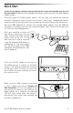
Quick Start 5. Plug receiver into audio system 6. Press Select button to change In order for your wireless system to work correctly, both the receiver and transmitter must be set to the same channel. Follow this basic procedure for setting up and using your AirLine 88 Headset wireless system: Physically place the CR88 receiver where it will be used, and extend the antennas vertically.
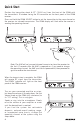
FREQ: 542-566MHz interference, and (2) this device must accept any interference received, including interference that may cause undesired operation. Quick Start Position the transmitter about 6-12” (15-30 cm) from the front of the CR88 with the transmitter’s IR window facing the IR transmitter on the front panel of the CR88 receiver. Press and hold the CR88 SELECT button to set the transmitter to the same channel as the receiver via infrared transmission.
Quick Start If you hear distortion at the desired volume level, check to see whether the PEAK Indicator LED on the receiver is lighting RED. If it is not lit, make sure that the gain structure of your audio system is set correctly (consult the owners manual of your mixer and/or amplifier for details). If the PEAK Indicator on the receiver lights RED, it may be as simple as moving the microphone further from your mouth.
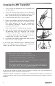
Charging the AH8 Transmitter 1. Snap in place the appropriate mains connector plug into the adapter. 2. Insert the magnetic power cable to the included USB AC plug (or any 5-volt DC adapter that has a USB port). Insert the AC plug into an electrical outlet. 3. Place the AH8 transmitter on a flat surface. 4. Attach the magnetic connector to the gold contact power port on the bottom of the AH8 transmitter. The cable attaches to the port magnetically.
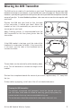
Wearing the AH8 Transmitter The AH8 can be re-sized to fit comfortably on your head. The correct way to wear your AH8 Headset transmitter is over the ears, as you would wear a pair of eyeglasses. Because the AH8 Headset is specially designed to be used up close, be sure to position the microphone near the corner of your lips. To avoid feedback problems, take care not to cover the mic capsule with your hand. Position the AH8 over your head so that the body of the transmitter is behind your head.
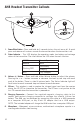
AH8 Headset Transmitter Callouts 1 4 3 5 2 6 1. Power/Mute Button - Press and hold for 3 seconds to turn the unit on or off. A quick press and release will mute or unmute the transmitter when the transmitter is on. 2. Status Indicator - This LED displays the operation mode, low battery and recharge status of the transmitter. The chart defines the LED colors for each function. GREEN Normal Operation AMBER Mute Flashing RED RED Low Battery Charging Fully Charged 3.
CR88 Receiver Front Callouts 1 2 3 4 5 6 7 8 1 1. Antennas - The antenna mountings allow full rotation for optimum placement. In normal operation, both antennas should be placed in a vertical position. Both antennas can be folded inward for convenience when transporting the CR88. 2. VOLUME Control - This knob sets the level of the audio signal being output through both the balanced and unbalanced output jacks on the rear panel.
CR88 Receiver Rear Callouts This device complies with Part 15 of the FCC Rules. Operation is subject to the following two conditions: (1) This device may not cause harmful interference, and (2) this device must accept any interference received, including interference that may cause undesired operation. FREQ: 542-566MHz 1 2 3 1. DC Input - Connect the supplied power adapter here, using the strain relief as shown in the illustration below. WARNING: Do not substitute any other kind of power adapter.
Rack Mounting The CR88 receiver can be installed into a standard 19” rack for transport or permanent installation using the included rack ears. Follow the simple steps below to mount the CR88: Attach the included rack ears by sliding each rack ear into the groove on either side of the CR88 until they lock into place, and the receiver flush with the front panel.
Channel Plans Group K 470-494 MHz Group D** 542-566 MHz Group G* 863-865 MHz Ch Freq Ch Freq Ch Freq 0 470.125 0 542.125 0 863.050 1 471.625 1 543.625 1 863.250 2 473.050 2 545.05 2 863.550 3 474.425 3 546.425 3 863.750 4 474.900 4 546.900 4 864.050 5 477.525 5 549.525 5 864.250 6 479.100 6 551.100 6 864.550 7 480.475 7 552.475 7 864.750 8 482.000 8 554.000 8 864.950 9 484.075 9 556.075 A 486.975 A 558.975 B 487.975 B 559.975 C 489.
Specifications System Working Range Audio Frequency Response T.H.D. (Overall) Dynamic Range Signal to Noise Operating Temperature Tone Key Frequency 300' (100m) line of sight 50 Hz - 15 kHz <1% (@AF 1 kHz, RF 46 dBu) >100 dB A-weighted >95 dB –10°C (14°F) to +60°C (+140°F) 32.768 kHz AH8 Headset Microphone Transmitter Microphone Element Condenser Mic Microphone Polar Pattern Unidirectional Input Gain Range 20dB RF Power 10mW EIRP Power Requirements 3.
Samson Technologies 45 Gilpin Avenue Hauppauge, New York 11788-8816 Phone: 1-800-3-SAMSON (1-800-372-6766) Fax: 631-784-2201 www.samsontech.