-5 -3 -2 -1 0 -20 +4 VU SAMSON OPTICAL COMPRESSOR A U D I O C Class Signal Processors -7 -10
Safety Instructions Caution: To reduce the hazard of electrical shock, do not remove cover or back. No user serviceable parts inside. Please refer all servicing to qualified personnel. WARNING: To reduce the risk of fire or electric shock, do not expose this unit to rain or moisture.
Table of Contents Introduction C com opti Features 4 5 Controls and Functions Front Panel Layout Rear Panel Layout 6 6 Operating the C com opti Setting Up the C com opti Compressing A Signal Using the Enhancer 7 8 9 System Set-ups 10 Dynamics Processing 101 11 Applications 12 C com opti Connections 13 Stacking and Installing the Tilting Feet 14 Installing the Optional CRK1 Dual Rack adapter 15 Specifications 16 C com opti Block Diagram 17 Copyright 2003, Samson Technologies Corp.
Introduction Congratulations on purchasing the C com opti, optical compressor by Samson Audio! The C com opti is a compact, high-quality device that provides extensive dynamics processing with a classic and musical response and with the warm sound that only a photo cell compressor can offer. Easy operation makes the C com opti the perfect solution for dynamics processing in live sound and in recording applications for tracking, mixing and mastering.
C com opti Features -7 -5 -3 -2 -1 0 -10 -20 +4 VU SAMSON The Samson C com opti optical compressor utilizes a unique photo cell design which produces a classic sound while handling the job of gain management . Here are some of its main features: • Full featured, optical compressor dynamics processor ideal for live sound and recording. • Unique photo gain cell design offering classic, musical response while controling signal levels.
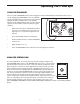
C com opti Layout Front Panel Layout 1 2 3 4 5 6 -7 -5 -3 -2 -1 0 -10 -20 +4 VU SAMSON 7 8 9 1 THRESHOLD - Used to set the minimum signal level at which the compressor circuit begins to function. 2 RATIO - Controls the amount of gain reduction in proportion to the amount of signal over the selected threshold level. 3 RELEASE - Adjusts the length of time the compressor takes to return the signal to it’s original level.
Operating The C com opti SETTING UP THE C com opti Setting up your C com opti is a simple procedure, which takes only a few minutes. There are many ways to interface the C com opti with various recording or live sound set-ups, so take some time to decide which audio devices you want to connect. The following section shows a simple set-up for a recording situation with a C com opti connected to a mixer’s insert points to compress an individual track, in this case a lead vocal.
Operating The C com opti COMPRESSING A SIGNAL C com opti’s compressor section can be used for a variety of gain management tasks including printing signals to a multi-track recorder, as a mix-down effect, mastering, and for increasing the loudness of a live PA system. To begin compressing your signal, follow the steps below: • Follow the section above, “SETTING UP THE C com opti” for normalizing the controls. • Press the BYPASS switch to the IN position.
Operating The C com opti USING THE ENHANCER The C com opti’s ENHANCER switch can be engaged to activate the EFR (Enhanced Frequency Recovery) circuit. By engaging the ENHANCER, the C com opti EFR restores the high frequency content that can be lost when high gain reduction is applied. The C com opti EFR achieves this by adding back the high-end of the original signal in an amount that is equal to the amount of gain reduction.
C com opti System Set-Ups INSERT POINT COMPRESSION -7 -5 -3 -2 -1 0 -7 -10 -5 -3 -2 -1 0 -10 -20 -20 +4 +4 VU VU SAMSON SAMSON In this example, two C com opti’s are used individually to compress the signal of the bass and keyboard tracks. The C com opti’s are connected to the mixer’s insert points using a standard 1/4-inch insert “Y” cable. See page 13 for a detailed wiring diagram.
Dynamics Processing 101 To begin to understand dynamics processing, we must first understand what dynamics are. Dynamics, or the dynamic range of a signal or audio device, is the amount of level between the softest and loudest possible output. Dynamics processing is applied to a signal to manage the changes in level. Various types of processing units are available to control dynamics including Noise Gates, Expanders, Compressors, Limiters and De-Essers.
Applications Leveling a Vocal Track When recording a vocal track, the vocalist may change the distance between them and the microphone, or they may naturally have a lot of dynamic range in their performance. In either case, the sound engineer must decide how much compression should be used to balance the natural performance and printing a good level to tape or disk. Set up the C com opti with a medium attack and release time and a ratio of 4:1. .
C com opti Connections CONNECTING THE C com opti The are several ways to interface the C com opti to support a variety of applications. The C com opti features servo-balanced inputs and outputs, so connecting balanced and unbalanced signals is possible without any signal loss. The C com opti can be used on a single instrument by connecting to a channel’s insert points, or on an entire mix "in-line" between a mixer’s outputs and a power amp or equalizer.
Stacking and Tilting the C com opti Stacking the C com opti You can stack one C com opti, or any other Samson C Class units, on top of each other by simply lining up the bumpers. Important Note: When stacking the C com opti, be sure that only the bottom unit has the tilting feet installed. Installing the Tilting Feet You can install the tilting rubber feet included with your C com opti so that you can set the unit at a comfortable operating angle on a workstation or desktop.
Installing the Optional CRK1 Dual Rack Adapter The C Class Dual Rack Adapter is available as an accessory from an authorized Samson dealer. 1. Disconnect any cables, that may be connected, from the C•Class unit to be mounted, i.e., the power supply cable, audio cables, headphones. 2. Align the holes in the C•Rack with the holes on the bottom of of the C•Class unit to be mounted. Use the supplied phillips head M4 machine screws to fix the unit to the rack as shown below. 3.
Specifications System Specifications Frequency Response Dynamic range Max Input Level Compressor Section Threshold Ratio Attack Time ReleaseTime Output gain Function Switch BYPASS Meter Enhancer Meters & LED's VU Meter 20Hz to 20kHz + - 0.5 dB 95 dBu, un-weighted, 22 Hz to 22 kHz +28 dBu -20 dB to +10 dB variable (1:5 to 5.1 ) variable (1 to 50 msec) variable (0.
C com opti Block Diagram 17
Notes 18
Samson Technologies Corp. 575 Underhill Blvd. P.O. Box 9031 Syosset, NY 11791-9031 Phone: 1-800-3-SAMSON (1-800-372-6766) Fax: 516-364-3888 www.samsontech.