
Operation Manual


Guided Tour - CRND Receiver
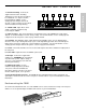
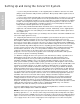
1: Antenna mounting - Connect the
supplied antenna to this mounting.
Third-party receiver antennas should
not
be substituted—use only the antenna
provided with the CRND. See the
“Setting Up and Using the Concert IV
System” section on page 6 for more about
antenna installation and positioning.
2: “TX ON” LED - Lights when carrier
signal of sufficient strength is being
received by the CRND.
3: Squelch control - This control determines the maximum range of the CRND before audio signal
dropout. It should normally be left at its factory setting. For more information, see the “Setting Up and
Using the Concert IV System” section on page 6 in this manual.
4: Peak LED - This LED lights when output signal from the CRND is at the onset of clipping (that is,
when it is on the verge of being distorted). If you see this light during operation, move the microphone
further away or lower the output level of your instrument or transmitter. For more information, see the
“Setting Up and Using the Concert IV System” section on page 6 in this manual.
5: Volume - This knob determines the level of the audio signal sent from the unbalanced output jack on
the rear panel.
6: Power LED - Lights whenever the CRND is powered on.
7: DC input - Connect the supplied AC
adapter here. WARNING: Do not substitute
any other kind of power adapter; doing so
can cause severe damage to the unit and
will void your warranty.
8: Unbalanced output - Use this
unbalanced high impedance (5K Ohm)
1/4" jack to connect the CRND to the
microphone input of your mixer. The jack is
wired as follows: tip hot, sleeve ground.
9: Rear-mount antenna knockout - The CRND antenna (normally mounted on the front panel) can
optionally be mounted on this area of the rear panel. Contact Samson or your local distributor for further
information.
Rack-mounting the CRND
As shown in the illustration below, one or two CRND receivers can be mounted in a single 19" rack space
with the use of an optional adapter available from Samson or your local distributor.
5
ENGLISH
min max
1
0
2
3
4
5
6
7
8
9
10
ANTENNA
VOLUME
SQUELCH
PEAK
TX ON
POWER
CONCERT
ND
SAMSON
VHF RECEIVER
Channel 16
2
1
3
4
5
6
UNBALANCED
OUTPUT
RECEIVER
SAMSON
MADE IN U.S.A.
ANTENNA
CAUTION USE 12 VDC
OUTPUT ADAPTER ONLY
PLUG LOCK
FOR AC
ADAPTER
DC INPUT 12V
1.2 W(100 mA)
-10 dBv 5 K Ω
+
-
7
8 9
m
in
m
a
x
1
0
2
3
4
5
6
7
8
9
1
0
ANTENN
A
VO
LUM
E
SQ
UE
LCH
PEA
K
TX O
N
PO
W
E
R
C
O
N
C
ER
T
lV
SAMSON
V
H
F
R
E
C
E
IV
E
R
Channel 16