
Operation Manual

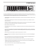
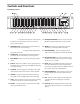

Table Of Contents
- Introduction
- Controls and Functions
- D1500 Quick Start
- Using the D1500 as an RTA.
- GLOBAL
- Selecting the Input
- Using the Microphone Input
- Operating the D1500
- MIDI and D Net
- Using the D1500 as a Signal Generator
- Using the D1500 as a VU Meter
- Operating the PHASE meter
- Using the D1500’s EQ Display
- FREQ – FREQUENCY
- HOLD
- RES – RESOLUTION
- REF - REFERENCE LEVEL
- WEIGHT
- INTEG – INTEGRATION
- DETECT
- GAIN
- SOURCE
- Adjusting the RTA parameters
- Using the ANALYZE Mode
- Operating the D1500 with the D2500 Digital EQ
- Operating the D1500 with the D2500 Equalizer
- Operating the D1500 with an Analog 31-band Equalizer
- Grounding Techniques
- D1500 Wiring Guide
- Specifications

5
Controls and Functions
Rear Panel Layout
19
EQ
– When selected, the unit is ready to display
the equalization curve from any connected
Samson Digital EQ.
20 PHASE
– When pressed in, the LED switch lights
indicating the operating mode is set to Phase
meter.
21 VU
– When engaged, the LED switch lights indi-
cating the operating mode is set to VU meter dis-
playing both PEAK and Average levels.
22 GEN (GENERATE)
– Press this button and the LED
will light indicating the Generator mode is select-
ed, making the Pink Noise and Sine wave genera-
tors ready for operation.
23 GLOBAL
– When engaged, the red LED will illumi-
nate indicating that the unit is in GLOBAL mode,
and that the operating system parameters are
under control and displayed in the LCD window.
24 MIDI switch
- This switch is used to page through
the MIDI parameters. When selected, the red LED
will illuminate and the MIDI parameters will be dis-
played in the LCD window.
25 LOAD switch
– Used to load one of the 100 pro-
grams from the internal memory.
26 STORE switch
- Used to store up to 99 programs
into the internal memory.
27 Main Level Meter
- Twelve segment LED meter
displays the input level.
A POWER SWITCH
– When set to the ON position, the
D1500 is powered up and ready for operation.
B MIDI IN DIN connector
– The D1500 receives standard, or
system exclusive, MIDI data here.
C MIDI OUT DIN connector
- The D1500 transmits standard,
or system exclusive, MIDI data here.
D MIDI THRU DIN connector
- The D1500 passes standard,
or system exclusive, MIDI data here.
E I/O Accessory Blank Panel
– Removable blanking panel
accesses option bay for adding additional Analog-to
Digital or Digital Input/Output boards.
F
AC input fuseholder
- Connect the supplied heavy
gauge 3-pin “IEC” power cable here.
G
D-NET Accessory Blank Panel
– removable blanking
panel accesses option bay for adding the DNET interface
card for controlling multiple D class units.
H ANALYZER MIC INPUT -
Balanced XLR microphone
input with phanom power.
I
CH1 Balanced XLR jack input
- Electronically bal-
anced XLR jack input.
J
CH2 Balanced XLR jack input
- Electronically bal-
anced XLR jack input.
K
CH1 Balanced XLR jack output
K CH1 Balanced XLR jack outputK
- Electronically
balanced XLR jack output.
L
CH2 Balanced XLR jack output
- Electronically bal-
anced XLR jack output.