
Operation Manual


4
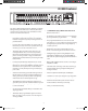
1 FILTER SELECT switch
– Each of the 30 filters can be
activated and set up by pressing the Filter Select switch.
2 DYNAMIC LED
– When the Red LED is lit, the filter is set
to Dynamic Mode.
3 RESONANCE LED
– Green LED indicating the filter is set
to Resonance Mode.
4 ACTIVE LED
– When the Amber LED is lit, the filter is set
to Actice Mode.
5 FREQUENC
Y
– Control knob, with LED light-ring posi-
tion
indicator
, used to set the center frequency of the
indicator, used to set the center frequency of the indicator
selected filter from 20 Hz to 20 kHz.
6 BANDWIDTH
– This control knob, with L
ED light-ring
position
indicator
, is used to adjust filter width and can
indicator, is used to adjust filter width and can indicator
be set from 1/60th of an octave to 1 octave.
7 GAIN
– Control knob, with L
ED light-ring position
indicator
, used to adjust the gain from +16 dB boost to
indicator, used to adjust the gain from +16 dB boost to indicator
–48dB cut.
8
LEVEL METER
- Twelve segment LED meter display the
input level and overload.
9 LCD DISPLAY
– Backlit display that shows the various
parameters under control by the operating system.
10 DATA WHEEL
– Rotary encoder for entering parameter
values.
11 BYPASS switch
– When the red LED is on, the digital
equalizer, as well as all the on-board digital processing
effects, are defeated.
12
A / B switch
– Used to switch between your modified
program, and the last program that has been loaded or
stored into memory.
Controls and Functions
Front Panel Layout
13 LEFT switch
– Assigns the Left (CH1) digital equal-
izer to the physical controls.
14
LINK switch
– Used to control the left and right
(CH1 and CH2) equalizer simultaneously with the
one set of physical controls.
15 RIGHT switch
- Assigns the Right (CH1) equalizer to
the physical controls.
16 RESET SWITCH
– Used to reset the selected filters
to 0 Gain.
17 FBM (Feedback Managment) switc
h
– Used to
set
Sensitivity, Hold and Release for
the automatic
feedback filter.
18 EQ switch
-- When engaged, the amber LED will illu-
minate indicating that the EQ parameters are under
control and displayed in the LCD window.
19 GATE switch
- Used to access the automatic GATE
control parameters. When selected, the amber LED
will illuminate and the associate values for the digi-
tal noise gate will be displayed in the LCD window.
20 DELAY switch
- When engaged, the amber LED will
illuminate indicating that the DELAY parameters are
under control and displayed in the LCD window.
21 ENHANCE switch
- When engaged, the amber LED
will illuminate indicating that the ENHANCE param-
eters are under control and displayed in the LCD
window.
22 HP / LP switch
– LED switch used to access the
HI PASS and LOW PASS control parameters. When
selected, the amber LED will illuminate and the
associated values for the high and low pass filters
will be displayed in the LCD window.
D3500_ownman_v1_2.indd 4 9/4/05 5:20:01 PM