A U D I O SOUND REINFORCEMENT 500 WATT Bi-AMPED ACTIVE LOUDSPEAKER
Safety Instructions/Consignes de sécurité/Sicherheitsvorkehrungen/Instrucciones de seguridad WARNING: To reduce the risk of fire or electric shock, do not expose this unit to rain or moisture. To reduce the hazard of electrical shock, do not remove cover or back. No user serviceable parts inside. Please refer all servicing to qualified personnel.
Table of Contents Introduction 2 dB500a Features 3 dB500a Layout Front View Layout Rear Panel Layout 4 5 Quick Set-up 6 Positioning the d500a 7 Operating the dB500a Controls and Functions Input and Output Connectors Setting Up Your dB500a System Using Speaker Stands Stacking the dB500a Permanent Installation 8-9 8 9 10-11 10 10 11 System Set-up Compact Lounge PA for Two Live Band PA System with Monitors 12 13 dB500a Wiring Guide 14 Specifications 15 Copyright 2002, Samson Technologies Corp
Introduction Congratulations on purchasing the Samson dB500a! The dB500a speaker system by Samson takes the concept of powered PA systems to a new level. By combining 500 watts of power, advanced active processing and the highest quality speaker and cabinet components, the dB500a provides studio quality sound for any kind of live application. The monitor features a super heavy-duty, custom designed 15-inch low frequency driver and a 1.
dB500a Features The Samson dB500a active two- way loudspeaker is an all-in-one solution for live sound. Here are some of its main features: • Two-way Active Loudspeaker – Standard speaker stand receptacle, 15 and 30 degree monitor angles, arrayable with 10 Fly Points. • Custom designed, heavy-duty, 15-inch low frequency driver with a 2.5-inch voice coil and 50 oz. magnet. • 1" Throat, high-frequency compression driver with 1.75-inch titanium diaphragm and 75 oz. magnet structure.
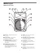
dB500a Layout dB500a Front View Layout 1 Enclosure – Rugged polypropylene plastic enclosure. 5 Handle – One of three, ultra oversized, rubber grip carry handles. 2 Stacking Bumper – Gender mating bumpers for stacking dB500’s. 6 Power LED – Blue Light Emitting Diode illuminates indicating the unit is powered on and ready for operation. 3 Wide Dispersion Horn – 1 inch throat, 60 x 90 degree wide dispersion horn provides extensive coverage and linear offaxis response.
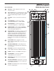
dB500a Layout dB500a Rear Panel Layout dB500a REAR PANEL 1 MIC LEVEL – Used to adjust the volume of the microphone input. 2 AMP / CLIP LED - Dual color LED lights Green when amp is active, flashes Red when the amp is clipped or stays Red indicating the amplifier is in protect mode.
Quick Set-Up In the following pages of this manual you will find a detailed explanation of all the dB500a’s functions and controls, but if you just want to get started quickly you can follow the steps below. IMPORTANT NOTE: To ensure the cleanest and loudest possible output, and to protect your speaker system, we highly recommend pressing the LIMITER switch on. Using a Microphone • Be sure that the dB500a’s Power switch is set to the off position.
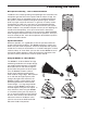
Positioning the dB500a Microphone Positioning - How to Reduce Feedback Feedback is the annoying howling and squealing that is heard when the microphone gets too close to the speaker and the volume is high. You get feedback when the microphone picks up the amplified signal from the speaker, and then amplifies through the speaker again, and then picks it up again, and so on and so on. In general, it is always recommended that any LIVE mic (a mic that’s on) is positioned behind the speaker enclosures.
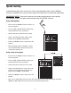
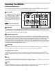
Operating the dB500a Controls and Functions The following section details each part of the dB500a’s INPUT section including the MIC and LINE inputs, the two-band EQ, as well as the MIC and LINE LEVEL controls. 1 MIC LEVEL The dB500a’s MIC LEVEL controls the overall level of the microphone input. The MIC LEVEL control features an audio taper. Raise the MIC Level to adjust the volume of the microphone connected to the MIC input.
Operating the dB500a Controls and Functions - continued 7 LOW FILTER The dB500a also incorporates a Low-cut FILTER which when engaged will roll off the low frequency response of the cabinet beginning at 80Hz. The low cut FILTER is two pole, which means that the low frequency roll off will gradually cut more and more of the low frequencies (12dB per octave). When you press the FILTER switch in, the green LED will illuminate indicating that the Low-cut FILTER is engaged.
Setting Up Your dB500a System Using Speaker Stands The dB500a enclosure features a standard 1 3/8”, pole mount receptacle, which is compatible with speaker stands from a variety of manufacturers. Before installing the dB500a on a speaker stand, loosen the thumbscrew located on the bottom of the rear side of the enclosure. Once installed on the stand, be sure to tighten the thumbscrew to hold the speaker in place. Be careful not to over tighten the thumbscrew to avoid stripping the threads.
Setting Up Your dB500a System Permanent Installation The dB500a is logical solution for many fixed installations in live sound venues, discos, schools, houses of worship, convention centers and airport terminals to name a few. The enclosure is extremely versatile for installation as it can be hung in several different positions by using the ten Fly-points.
dB500a System Set Compact Lounge PA for Two This example shows a PA system set-up that can be used for a small club, at a ceremony or in a lounge, using a single dB500a for both a microphone and vocal. A separate signal is sent from the vocal microphone to the dB500a’s Mic input, and from the keyboard to the dB500a’s Line input. The individual Mic and Line level controls allow you to create a mix right on the dB500a.
This example shows a typical PA system using mixer with a pair of dB500a’s for the main left and right mix. A separate signal from the mixer’s AUX/MONITOR bus is sent to two additional dB500a’s placed in the tilt-back, wedge positions for use as floor monitors. In order to increase the output of the monitor system, the use of an external graphic equalizer like one of the Samson “E” or “S curve” series is highly recommended.
dB500a Wiring Guide CONNECTING THE dB500a The are several ways to interface the dB500a to support a variety of applications. The dB500a features balanced inputs and outputs, so connecting balanced and unbalanced signals is possible.
dB500a Specifications Inputs Microphone Line Balanced XLR Balanced Combo XLR/Line Outputs Extension Balanced XLR Controls Mic Level Line Level Low EQ High-EQ Low Filter Switch Output Switch Limiter Switch Rotary Rotary Rotary Center Detent, +/-12dB @100Hz Rotary Center Detent, +/-12dB @ 10kHz Push Switch, High Pass (low-cut) 12dB per octave @80Hz Push Switch, Selects Mix orThru for Line Output Connector Push Switch, Optimax Multi-band dynamics - In/Out Power Rating: Low Frequency High Frequency 400 W
Notes 16
Samson Technologies Corp. 575 Underhill Blvd. P.O. Box 9031 Syosset, NY 11791-9031 Phone: 1-800-3-SAMSON (1-800-372-6766) Fax: 516-364-3888 www.samsontech.